
Datasheet


DS28E05 1-Wire EEPROM
www.maximintegrated.com
Maxim Integrated
│
10
Read Memory [F0h]
TheReadMemorycommandisusedtoreadthememory.Thecommandneedsa16-bitstartingaddressTA1,TA2.The
parameterbytespecifiestheloweraddressbyte(TA1,T[6:0])wherethereadingbegins.Aftertheparameterbyte,the
mastertransmitsTA2(T[15:8]),whichmustbe00tobevalid.Thereadingcanstartatanyvalidstartingaddressand
continuetroughtheendofthememory.Ifmemorypage7isreadandthemastercontinuesreading,theresultingdata
isFFh.ThemastercanendtheReadMemorycommandatanytimebyissuingaresetpulse.
1-Wire Bus System
The 1-Wire bus is a system that has a single bus master
and one or more slaves. In all instances the DS28E05
is a slave device. The discussion of this bus system is
broken down into three topics: hardware configuration,
transactionsequence,and1-Wiresignaling(signaltypes
and timing). The 1-Wire protocol defines bus transactions
intermsofthebusstateduringspecifictimeslots,which
are initiated on the falling edge of sync pulses from the
bus master.
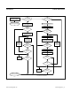
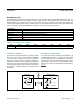
Hardware Conguration
The1-Wirebushasonlyasinglelinebydefinition;itis
important that each device on the bus be able to drive
itat the appropriate time. To facilitate this, each device
attached to the 1-Wire bus must have open-drain or three-
state outputs. The 1-Wire port of the DS28E05 is open
drain with an internal circuit equivalent to that shown in
Figure7.
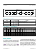
Table 4. Parameter Byte Bitmap
Note: The bit marked as 0 must be transmitted as 0 for the parameter byte to be valid.
Figure 7. Hardware Configuration
Read Memory
CommandCode F0h
ParameterByte Starting memory address (Table 4).
Restrictions
None.Thiscommandcanbeissuedatanytime.
ProtocolVariations None.
Error conditions Invalid parameter byte.
CSByte N/A
BIT 7 BIT 6 BIT 5 BIT 4 BIT 3 BIT 2 BIT 1 BIT 0
0 TA1
Rx
R
PUP
I
L
V
PUP
BUS MASTER
OPEN-DRAIN
PORT PIN
100
Ω MOSFET
Tx
Rx
Tx
DATA
DS28E05 1-Wire PORT
Rx = RECEIVE
Tx = TRANSMIT