
Datasheet


DS28E04-100: 4096-Bit 1-Wire Addressable EEPROM with PIO
6 of 37
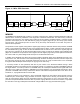
Figure 2. Hierarchical Structure for 1-Wire Protocol
DS28E04-100
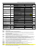
Available
Commands:
Command
Level:
Data Field
Affected:
1-Wire ROM Function
Commands (see Figure 14)
DS28E04
-Specific
Memory/Control Function
Commands (see Figure 9)
Read ROM
Match ROM
Search ROM
Conditional Search
ROM
Skip ROM
Resume
Overdrive Skip
Overdrive Match
Device ID, RC-Flag
Device ID, RC
-Flag
Device ID, RC-Flag
Device ID, RC-Flag, PIO Status,
cond. Search Settings
RC-Flag
RC-Flag
RC-Flag, OD-Flag
Device ID, RC-Flag, OD-Flag
Write Scratchpad
Read Scratchpad
Copy Scratchpad
Read Memory
PIO Access Read
PIO Access Write
PIO Access Pulse
Reset Act. Latch
Write Register
32-byte Scratchpad, Flags
32-byte Scratchpad
Data Memory, Register Page
Data Memory, Registers
PIO Pins
PIO Pins, Activity Latch
PIO Pins, Activity Latch
Activity Latch
Conditional Search and Control
Registers
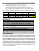
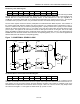
64-BIT DEVICE ID NUMBER (NETWORK ADDRESS)
Each DS28E04-100 has a unique device ID number that is 64 bits long, as shown in Figure 3. The first 8 bits are a
1-Wire family code. The next 8 bits are an external address byte, of which the lower 7 bits are connected to the
address input pins A0 to A6. This allows the user to set a portion of the Device ID Number by connecting some of
these pins to GND (logic 0) or to V
CC
(logic 1) or leaving them open (logic 1). The next 40 bits are a lasered serial
number. Even if multiple DS28E04-100 are used in a 1-Wire network and all address inputs are wired to the same
state or left open (unconnected), the unique 40-bit serialization field will prevent any address conflict, allowing to
communicate with each device individually. The last 8 bits are a lasered CRC (Cyclic Redundancy Check) of the
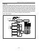
first 56 bits, assuming that the address input pins A0 to A6 are at logic 1. The 1-Wire CRC is generated using a
polynomial generator consisting of a shift register and XOR gates as shown in Figure 4. The polynomial is X
8
+ X
5
+
X
4
+ 1. Further information on the Device ID CRC is found in section CRC Generation near the end of this
document.
Figure 3. 64-Bit Device ID Number
MSB
LSB
8-Bit CRC
Code
40-Bit Lasered Serial Number
8-Bit External
Address Input
8-Bit Family Code
(1Ch)
0
A
6
A
5
A
4
A
3
A
2
A
1
A
0
MSB LSB
MSB LSB
MSB LSB
MSB LSB