
Datasheet


DS28E04-100: 4096-Bit 1-Wire Addressable EEPROM with PIO
35 of 37
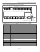
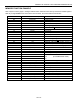
PIO ACCESS READ EXAMPLE
Read the state of the PIOs 32 times.
With only a single DS28E04-100
connected to the bus master, the communication looks like this:
MASTER MODE
DATA (LSB FIRST)
COMMENTS
TX
(Reset)
Reset pulse
RX
(Presence)
Presence pulse
TX
CCh
Issue “Skip ROM” command
TX
F5h
Issue “PIO Access Read” command
RX
<32 data bytes>
Read 32 PIO samples
RX
<2 bytes CRC16\>
Read CRC to check for data integrity
TX
(Reset)
Reset pulse
RX
(Presence)
Presence pulse
The inverted CRC16 is transmitted after 32 bytes of PIO data.
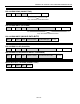
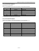
PIO ACCESS WRITE EXAMPLE
Set both PIOs to 0 and then to 1. Both PIOs are pulled high to V
CC
or V
PUP
by a resistor.
With only a single DS28E04-100
connected to the bus master, the communication looks like this:
MASTER MODE
DATA (LSB FIRST)
COMMENTS
TX
(Reset)
Reset pulse
RX
(Presence)
Presence pulse
TX
CCh
Issue “Skip ROM” command
TX
5Ah
Issue “PIO Access Write” command
TX
FCh
Write new PIO output state
TX
03h
Write inverted new PIO output state
RX
AAh
Read confirmation byte
RX
FCh
Read new PIO pin status
TX
FFh
Write new PIO output state
TX
00h
Write inverted new PIO output state
RX
AAh
Read confirmation byte
RX
FFh
Read new PIO pin status
TX
(Reset)
Reset pulse
RX
(Presence)
Presence pulse