
Datasheet


DS28E04-100: 4096-Bit 1-Wire Addressable EEPROM with PIO
27 of 37
OVERDRIVE MATCH ROM [69h]
The Overdrive Match ROM command followed by a 64-bit ROM sequence transmitted at Overdrive speed allows
the bus master to address a specific DS28E04-100 on a multidrop bus and to simultaneously set it in Overdrive
mode. Only the DS28E04-100 that exactly matches the 64-bit ROM sequence responds to the subsequent
Memory/Control Function command. Slaves already in Overdrive mode from a previous Overdrive Skip or
successful Overdrive Match command remain in Overdrive mode. All overdrive-capable slaves return to standard
speed at the next Reset Pulse of minimum 480µs duration. The Overdrive Match ROM command can be used with
a single or multiple devices on the bus.
1-Wire SIGNALING
The DS28E04-100 requires strict protocols to ensure data integrity. The protocol consists of four types of signaling
on one line: Reset Sequence with Reset Pulse and Presence Pulse, Write-Zero, Write-One, and Read-Data.
Except for the Presence pulse, the bus master initiates all falling edges. The DS28E04-100 can communicate at
two different speeds, standard speed, and Overdrive speed. If not explicitly set into the Overdrive mode, the
DS28E04-100 communicates at standard speed. While in Overdrive Mode, the fast timing applies to all waveforms.
To get from idle to active, the voltage on the 1-Wire line needs to fall from V
PUP
below the threshold V
TL
. To get
from active to idle, the voltage needs to rise from V
ILMAX
past the threshold V
TH
. The time it takes for the voltage to
make this rise is seen in Figure 15 as 'ε' and its duration depends on the pullup resistor (R
PUP
) used and the
capacitance of the 1-Wire network attached.
The voltage V
ILMAX
is relevant for the DS28E04-100 when determining
a logical level, not triggering any events.
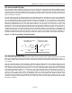
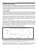
Figure 15 shows the initialization sequence required to begin any communication with the DS28E04-100. A Reset
Pulse followed by a Presence Pulse indicates the DS28E04-100 is ready to receive data, given the correct ROM
and Memory/Control Function command. If the bus master uses slew-rate control on the falling edge, it must pull
down the line for t
RSTL
+ t
F
to compensate for the edge. A t
RSTL
duration of 480µs or longer exits the Overdrive
Mode, returning the device to standard speed. If the DS28E04-100 is in Overdrive Mode and t
RSTL
is no longer than
80µs, the device remains in Overdrive Mode. If the device is in Overdrive Mode and t
RSTL
is between 80µs and
480µs, the device will reset, but the communication speed is undetermined.
Figure 15. Initialization Procedure: Reset and Presence Pulse
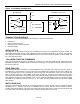
After the bus master has released the line, it goes into receive mode. Now the 1-Wire bus is pulled to V
PUP
through
the pullup resistor, or in case of a DS2482-x00 or DS2480B driver, by active circuitry. When the threshold V
TH
is
crossed, the DS28E04-100 waits for t
PDH
and then transmits a Presence Pulse by pulling the line low for t
PDL
. To
detect a presence pulse, the master must test the logical state of the 1-Wire line at t
MSP
.
The t
RSTH
window must be at least the sum of t
PDHMAX
, t
PDLMAX
, and t
RECMIN
. Immediately after t
RSTH
is expired, the
DS28E04-100 is ready for data communication. In a mixed population network, t
RSTH
should be extended to
minimum 480µs at standard speed and 48µs at Overdrive speed to accommodate other 1-Wire devices.