
Datasheet


DS28E04-100: 4096-Bit 1-Wire Addressable EEPROM with PIO
11 of 37
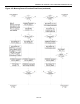
Conditional Search Channel Polarity Selection Register
ADDR
b7
b6
b5
b4
b3
b2
b1
b0
0224h
0
0
0
0
0
0
SP1
SP0
The data in this register specifies the polarity of each selected PIO channel for the device to respond to the
conditional search command. This register can only be written through the Write Registers command. Within a PIO
channel, the data source may be either the channel's input pin or the channel's activity latch, as specified by the
PLS bit in the Control/Status register at address 0225h. This register is read/write. Each bit is associated with the
respective PIO channel as shown in Figure 7. Bits 2 to 7 have no function; they always read 0 and cannot be
changed to 1. This register is cleared to 00h at power-up.
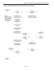
Control/Status Register
ADDR
b7
b6
b5
b4
b3
b2
b1
b0
0225h
VCCP
POL
0
0
PORL
0
CT
PLS
The data in this register reports status information and further configures the device for conditional search. This
register can only be written through the Write Registers command. This register is read/write. The power-up state
of the PORL bit is "1". CT and PLS power up as "0". The functional assignments of the individual bits are explained
in the table below. Bits 2, 4, and 5 have no function; they always read 0 and cannot be set to 1.
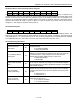
Control/Status Register Details
BIT DESCRIPTION
BIT(S)
DEFINITION
PLS: Pin or Activity
Latch Select
b0
Selects either the PIO pins or the PIO activity latches as input for the
conditional search.
0: pin selected (default)
1: activity latch selected
CT: Conditional Search
Logical Term
b1
Specifies whether the data of two channels needs to be ORed or
AND’ed to meet the qualifying condition for the device to respond to
a conditional search. If only a single channel is selected in the
channel selection mask (0223h) this bit is a don't care.
0: bitwise OR (default)
1: bitwise AND
PORL: Power-On Reset
Latch
b3
Specifies whether the device has performed a power-on reset. This
bit can only be cleared to 0 by writing to the Control/Status Register.
As long as this bit is 1 the device will always respond to a Conditional
Search ROM sequence.
POL: PIO Default
Polarity (Read-Only)
b6
Reports the state of the POL pin. The state of the POL pin specifies
whether the PIO pins P0 and P1 power up high or low. The polarity
of a pulse generated at a PIO pin is the opposite of the pin's power-
up state.
0: PIO powers up 0
1: PIO powers up 1
VCCP: V
CC
Power
Status (Read-Only)
b7
For V
CC
-powered operation, the V
CC
pin needs to be connected to a
voltage source equal to V
PUP
.
0: V
CC
power not available
1: V
CC
-powered operation