
Datasheet


DS2780 Standalone Fuel Gauge IC
21 of 31
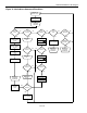
the RARC result crosses 4% boundaries. This allows the DS2780 to be located outside the protection FETs. In this
manner, if a protection device is triggered, the DS2780 cannot lose more that 4% of charge or discharge data.
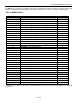
Table 2. MEMORY MAP
ADDRESS (HEX) DESCRIPTION READ/WRITE
00 Reserved R
01 STATUS - Status Register R/W
02 RAAC - Remaining Active Absolute Capacity MSB R
03 RAAC - Remaining Active Absolute Capacity LSB R
04 RSAC - Remaining Standby Absolute Capacity MSB R
05 RSAC - Remaining Standby Absolute Capacity LSB R
06 RARC - Remaining Active Relative Capacity R
07 RSRC - Remaining Standby Relative Capacity R
08 IAVG - Average Current Register MSB R
09 IAVG - Average Current Register LSB R
0A TEMP - Temperature Register MSB R
0B TEMP - Temperature Register LSB R
0C VOLT - Voltage Register MSB R
0D VOLT - Voltage Register LSB R
0E CURRENT - Current Register MSB R
0F CURRENT - Current Register LSB R
10 ACR - Accumulated Current Register MSB R/W*
11 ACR - Accumulated Current Register LSB R/W *
12 ACRL – Low Accumulated Current Register MSB R
13 ACRL – Low Accumulated Current Register LSB R
14 AS - Age Scalar R/W *
15 SFR - Special Feature Register R/W
16 FULL - Full Capacity MSB R
17 FULL - Full Capacity LSB R
18 AE - Active Empty MSB R
19 AE - Active Empty LSB R
1A SE - Standby Empty MSB R
1B SE - Standby Empty LSB R
1C to 1E Reserved —
1F EEPROM - EEPROM Register R/W
20 to 2F User EEPROM, Lockable, Block 0 R/W
30 to 5F Reserved —
60 to 7F Parameter EEPROM, Lockable, Block 1 R/W
80 to FF Reserved —
* Register value is automatically saved to EEPROM during ACTIVE mode operation and recalled from EEPROM
on power up.