
Datasheet
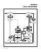


1-Wire 4Kb EEPROM
1-Wire Signaling
The DS24B33 requires strict protocols to ensure data
integrity. The protocol consists of four types of signaling
on one line: reset sequence with reset pulse and pres-
ence pulse, write-zero, write-one, and read-data.
Except for the presence pulse, the bus master initiates
all falling edges. The DS24B33 can communicate at
two different speeds: standard speed and overdrive
speed. If not explicitly set into the overdrive mode, the
DS24B33 communicates at standard speed. While in
overdrive mode the fast timing applies to all waveforms.
To get from idle to active, the voltage on the 1-Wire line
needs to fall from V
PUP
below the threshold V
TL
. To get
from active to idle, the voltage needs to rise from
V
ILMAX
past the threshold V
TH
. The time it takes for the
voltage to make this rise is seen in Figure 10 as ε, and
its duration depends on the pullup resistor (R
PUP
) used
and the capacitance of the 1-Wire network attached.
The voltage V
ILMAX
is relevant for the DS24B33 when
determining a logical level, not triggering any events.
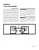
Figure 10 shows the initialization sequence required to
begin any communication with the DS24B33. A reset
pulse followed by a presence pulse indicates that the
DS24B33 is ready to receive data, given the correct
ROM and memory function command. If the bus master
uses slew-rate control on the falling edge, it must pull
down the line for t
RSTL
+ t
F
to compensate for the edge.
A t
RSTL
duration of 480µs or longer exits the overdrive
mode, returning the device to standard speed. If the
DS24B33 is in overdrive mode and t
RSTL
is no longer
than 80µs, the device remains in overdrive mode. If the
device is in overdrive mode and t
RSTL
is between 80µs
and 480µs, the device resets, but the communication
speed is undetermined.
After the bus master has released the line it goes into
receive mode. Now the 1-Wire bus is pulled to V
PUP
through the pullup resistor, or in case of a DS2482-x00
or DS2480B driver, by active circuitry. When the thresh-
old V
TH
is crossed, the DS24B33 waits for t
PDH
and
then transmits a presence pulse by pulling the line low
for t
PDL
. To detect a presence pulse, the master must
test the logical state of the 1-Wire line at t
MSP
.
The t
RSTH
window must be at least the sum of t
PDHMAX
,
t
PDLMAX
, and t
RECMIN
. Immediately after t
RSTH
is
expired, the DS24B33 is ready for data communication.
In a mixed population network, t
RSTH
should be extend-
ed to minimum 480µs at standard speed and 48µs at
overdrive speed to accommodate other 1-Wire devices.
Read/Write Time Slots
Data communication with the DS24B33 takes place in
time slots, which carry a single bit each. Write time slots
transport data from bus master to slave. Read time
slots transfer data from slave to master. Figure 11 illus-
trates the definitions of the write and read time slots.
All communication begins with the master pulling the
data line low. As the voltage on the 1-Wire line falls
below the threshold V
TL
, the DS24B33 starts its internal
timing generator that determines when the data line is
sampled during a write time slot and how long data is
valid during a read time slot.
Master-to-Slave
For a write-one time slot, the voltage on the data line
must have crossed the V
TH
threshold before the write-
one low time t
W1LMAX
is expired. For a write-zero time
slot, the voltage on the data line must stay below the
V
TH
threshold until the write-zero low time t
W0LMIN
is
expired. For the most reliable communication, the
RESISTOR MASTER DS24B33
t
RSTL
t
PDL
t
RSTH
t
PDH
MASTER Tx "RESET PULSE" MASTER Rx "PRESENCE PULSE"
V
PUP
V
IHMASTER
V
TH
V
TL
V
ILMAX
0V
ε
t
F
t
REC
t
MSP
Figure 10. Initialization Procedure: Reset and Presence Pulse
Maxim Integrated
17
DS24B33