
Datasheet


2
3
1
2
3
1
3
2
1
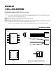
N.C.
IO
GND
TO-92
FRONT VIEW (T&R VERSION)
FRONT VIEWSIDE VIEW
1
2
3
4
N.C.
N.C.
IO
GND
N.C.
N.C.
N.C.
N.C.
NOTE: THE SFN PACKAGE IS QUALIFIED FOR ELECTRO-MECHANICAL CONTACT
APPLICATIONS ONLY, NOT FOR SOLDERING. FOR MORE INFORMATION, REFER TO
APPLICATION NOTE 4132: ATTACHMENT METHODS FOR ELECTRO-MECHANICAL
SFN PACKAGE.
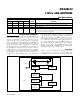
8
7
6
5
DS24B33
SO
(208 mils)
TOP VIEW
+
SFN
(6mm × 6mm × 0.9mm)
BOTTOM VIEW
12
IO GND
DS24B33
DS24B33
16N.C. N.C.
25IO N.C.
34GND N.C.
TDFN
(3mm
× 3mm)
TOP VIEW
24B33
ymrrF
+
*EP
*EXPOSED PAD
ELECTRICAL CHARACTERISTICS (continued)
(T
A
= -40°C to +85°C.) (Note 1)
Note 19: The t
PROG
interval begins after the trailing rising edge on IO for the last time slot of the E/S byte for a valid copy scratch-
pad sequence. The interval ends once the device’s self-timed EEPROM programming cycle is complete and the current
drawn by the device has returned from I
PROG
to I
L
.
Note 20: Write-cycle endurance is degraded as T
A
increases.
Note 21: Not 100% production tested; guaranteed by reliability monitor sampling.
Note 22: Data retention is degraded as T
A
increases.
Note 23: Guaranteed by 100% production test at elevated temperature for a shorter time; equivalence of this production test to data
sheet limit at operating temperature range is established by reliability testing.
Note 24: EEPROM writes can become nonfunctional after the data-retention time is exceeded. Long-time storage at elevated tem-
peratures is not recommended; the device can lose its write capability after 10 years at +125°C or 40 years at +85°C.
1-Wire 4Kb EEPROM
Pin Configurations
4
Maxim Integrated
DS24B33