
Datasheet


1-Wire 4Kb EEPROM
1ST
STAGE
2ND
STAGE
3RD
STAGE
4TH
STAGE
7TH
STAGE
8TH
STAGE
6TH
STAGE
5TH
STAGE
X
0
X
1
X
2
X
3
X
4
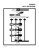
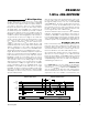
POLYNOMIAL = X
16
+ X
15
+ X
2
+ 1
INPUT DATA
CRC OUTPUT
X
5
X
6
11TH
STAGE
12TH
STAGE
15TH
STAGE
14TH
STAGE
13TH
STAGE
X
11
X
12
9TH
STAGE
10TH
STAGE
X
9
X
10
X
13
X
14
X
7
16TH
STAGE
X
16
X
15
X
8
Figure 13. CRC-16 Hardware Description and Polynomial
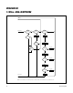
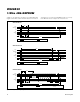
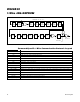
SYMBOL DESCRIPTION
RST 1-Wire reset pulse generated by master
PD 1-Wire presence pulse generated by slave
Select Command and data to satisfy the ROM function protocol
WS Command: “Write Scratchpad”
RS Command: “Read Scratchpad”
CPS Command: “Copy Scratchpad”
RM Command: “Read Memory”
TA Target Address TA1, TA2
TA-E/S Target Address TA1, TA2 with E/S byte
<data to EOS> Transfer of as many bytes as needed to reach the end of the scratchpad for a given target address
<data to EOM> Transfer of as many bytes as are needed to reach the end of the memory
CRC-16 Transfer of an inverted CRC-16
FF loop Indefinite loop where the master reads FF bytes
AA loop Indefinite loop where the master reads AA bytes
Programming Data transfer to EEPROM; no activity on the 1-Wire bus permitted during this time
Command-Specific 1-Wire Communication Protocol—Legend
20
Maxim Integrated
DS24B33