
Datasheet


Maxim Integrated | 5www.maximintegrated.com
DS2482-100
Single-Channel 1-Wire Master
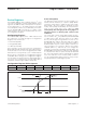
Pin Description
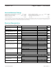
PIN
SO WLP
NAME FUNCTION
1 B3 V
CC
Power-Supply Input
2 C3 IO Input/Output Driver for 1-Wire Line
3 C2 GND Ground Reference
4 B1 SCL I
2
C Serial Clock Input. Must be connected to V
CC
through a pullup resistor.
5 B2 SDA I
2
C Serial Data Input/Output. Must be connected to V
CC
through a pullup resistor.
6 A1 PCTLZ
Active-Low Control Output for an External p-Channel MOSFET. Provides extra power to the 1-Wire
line, e.g., for use with 1-Wire devices that require a higher current temporarily to operate.
7 A2 AD1
8 A3 AD0
I
2
C Address Inputs. Must be connected to V
CC
or GND. These inputs determine the I
2
C slave
address of the device (see Figure 8).
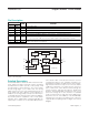
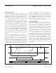
CONFIGURATION
REGISTER
I
2
C
INTERFACE
CONTROLLER
INPUT/OUTPUT
CONTROLLER
LINE
XCVR
T-TIME OSC
DS2482-100
STATUS
REGISTER
READ DATA
REGISTER
SDA
IO
PCTLZ
AD0
AD1
SCL
Figure 1. Block Diagram
Detailed Description
The DS2482-100 is a self-timed 1-Wire master that sup-
ports advanced 1-Wire waveform features including
standard and overdrive speeds, active pullup, and
strong pullup for power delivery. The active pullup
affects rising edges on the 1-Wire side. The strong
pullup function uses the same pullup transistor as the
active pullup, but with a different control algorithm. In
addition, the strong pullup activates the PCTLZ pin,
controlling optional external circuitry to deliver addition-
al power beyond the capabilities of the on-chip pullup
transistor. Once supplied with command and data, the
input/output controller of the DS2482-100 performs
time-critical 1-Wire communication functions such as
reset/presence-detect cycle, read-byte, write-byte, sin-
gle-bit R/W, and triplet for ROM Search, without requir-
ing interaction with the host processor. The host obtains
feedback (completion of a 1-Wire function, presence
pulse, 1-Wire short, search direction taken) through the
Status Register and data through the Read Data
Register. The DS2482-100 communicates with a host
processor through its I
2
C bus interface in standard
mode or in fast mode. The logic state of two address pins
determines the I
2
C slave address of the DS2482-100,
allowing up to four devices operating on the same bus
segment without requiring a hub. See Figure 1 for a block
diagram.