
Datasheet


Maxim Integrated | 20www.maximintegrated.com
DS2482-100
Single-Channel 1-Wire Master
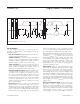
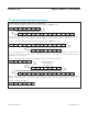
1-Wire Read Byte (To Read a Byte from the 1-Wire Line)
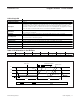
Case A: 1-Wire Idle (1WB = 0), No Busy Polling, Set Read Pointer After Idle Time
The idle time is needed for the 1-Wire function to complete. Then set the read pointer to the Read Data Register
(code E1h) and access the device again to read the data byte that was obtained from the 1-Wire line.
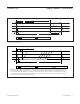
Case B: 1-Wire Idle (1WB = 0), No Busy Polling, Set Read Pointer Before Idle Time
The read pointer is set to the Read Data Register (code E1h) while the 1-Wire Read Byte command is still in
progress. Then, after the 1-Wire function is completed, the device is accessed to read the data byte that was
obtained from the 1-Wire line.
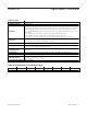
Case C: 1-Wire Idle (1WB = 0), Busy Polling Until the 1-Wire Command is Completed
Poll the Status Register until the 1WB bit has changed from 1 to 0. Then set the read pointer to the Read Data
Register (code E1h) and access the device again to read the data byte that was obtained from the 1-Wire line.
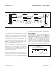
Case D: 1-Wire Busy (1WB = 1)
The master should stop and restart as soon as the DS2482-100 does not acknowledge the command code.
S AD,0 A 1WRB A\ P
S AD,0 A 1WRB
AD,0 A SRP
A
A E1h A
Sr AD,1 A <byte> A
Sr AD,1 A <byte> A\ P
<byte> A\
REPEAT UNTIL THE 1WB BIT
HAS CHANGED TO 0.
Sr
S AD,0 A 1WRB A Sr AD,0 A SRP E1h A PA
(Idle) S AD,1 A <byte> PA\
S AD,0 A 1WRB A P (Idle)
S AD,0 A SRP AD,1 A <byte>A E1h A Sr PA\
I
2
C Communication Examples (continued)