
Datasheet


Maxim Integrated | 18www.maximintegrated.com
DS2482-100
Single-Channel 1-Wire Master
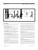
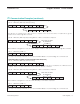
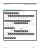
Device Reset (After Power-Up)
Activities that are underlined denote an optional read access to verify the success of the command.
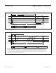
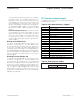
Set Read Pointer (To Read from Another Register)
Case A: Valid Read Pointer Code
C3h is the valid read pointer code for the Configuration Register.
Case B: Invalid Read Pointer Code
E5h is an invalid read pointer code.
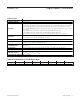
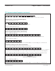
Write Configuration (Before Starting 1-Wire Activity)
Case A: 1-Wire Idle (1WB = 0)
Activities that are underlined denote an optional read access to verify the success of the command.
Case B: 1-Wire Busy (1WB = 1)
The master should stop and restart as soon as the DS2482-100 does not acknowledge the command code.
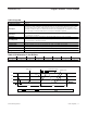
1-Wire Reset (To Begin or End 1-Wire Communication)
Case A: 1-Wire Idle (1WB = 0), No Busy Polling to Read the Result
In the first cycle, the master sends the command. Then the master waits (Idle) for the 1-Wire reset to complete. In
the second cycle, the DS2482-100 is accessed to read the result of the 1-Wire reset from the Status Register.
Case B: 1-Wire Idle (1WB = 0), Busy Polling Until the 1-Wire Command is Completed, then Read the Result
Case C: 1-Wire Busy (1WB = 1)
The master should stop and restart as soon as the DS2482-100 does not acknowledge the command code.
S AD,0 A 1WRS A\ P
S AD,0 A 1WRS A <byte> A
REPEAT UNTIL THE 1WB BIT HAS CHANGED TO 0.
<byte>AA\Sr PAD,1
S AD,0 A 1WRS S AD,1 A <byte>AA\P P(Idle)
S AD,0 A WCFG A\ P
S AD,0 A WCFG A A Sr AD,1 A <byte> A\ P<byte>
S AD,0 A SRP AA\E5h P
S AD,0 A SRP AAC3h P
S AD,0 A DRST A Sr AD,1 A <byte> A\ P
I
2
C Communication Examples (continued)