
Datasheet


Maxim Integrated | 17www.maximintegrated.com
DS2482-100
Single-Channel 1-Wire Master
some time later the slave may refuse to accept data,
possibly because of an invalid command code or
parameter. In this case, the slave device does not
acknowledge any of the bytes that it refuses and
leaves SDA high. In either case, after a slave has
failed to acknowledge, the master first should gener-
ate a repeated START condition or a STOP condition
followed by a START condition to begin a new data
transfer.
Not Acknowledged by Master: At some time when
receiving data, the master must signal an end of
data to the slave device. To achieve this, the master
does not acknowledge the last byte that it has
received from the slave. In response, the slave
releases SDA, allowing the master to generate the
STOP condition.
Writing to the DS2482-100
To write to the DS2482-100, the master must access
the device in write mode, i.e., the slave address must
be sent with the direction bit set to 0. The next byte to
be sent is a command code, which, depending on the
command, may be followed by a command parameter.
The DS2482-100 acknowledges valid command codes
and expected/valid command parameters. Additional
bytes or invalid command parameters are never
acknowledged.
Reading from the DS2482-100
To read from the DS2482-100, the master must access
the device in read mode, i.e., the slave address must
be sent with the direction bit set to 1. The read pointer
determines the register that the master reads from. The
master can continue reading the same register over
and over again, without having to readdress the device,
e.g., to watch the 1WB changing from 1 to 0. To read
from a different register, the master must issue the Set
Read Pointer command and then access the DS2482-
100 again in read mode.
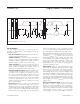
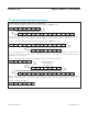
I
2
C Communication Example
See Tables 4 and 5 for the I
2
C communication legend
and data direction codes.
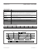
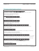
Table 4. I
2
C Communication—Legend
SYMBOL DESCRIPTION
S START Condition
AD, 0 Select DS2482-100 for Write Access
AD, 1 Select DS2482-100 for Read Access
Sr Repeated START Condition
P STOP Condition
A Acknowledged
A\ Not Acknowledged
(Idle) Bus Not Busy
<byte> Transfer of One Byte
DRST Command “Device Reset”, F0h
SRP Command “Set Read Pointer”, E1h
WCFG Command “Write Configuration”, D2h
1WRS Command “1-Wire Reset”, B4h
1WSB Command “1-Wire Single Bit”, 87h
1WWB Command “1-Wire Write Byte”, A5h
1WRB Command “1-Wire Read Byte”, 96h
1WT Command “1-Wire Triplet”, 78h
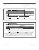
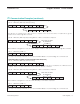
Table 5. Data Direction Codes
Master-to-Slave Slave-to-Master