
Datasheet


Maxim Integrated | 14www.maximintegrated.com
DS2482-100
Single-Channel 1-Wire Master
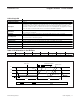
1-Wire Triplet
Command Code 78h
Command Parameter Direction Byte
Description
Generates three time slots: two read time slots and one write time slot at the 1-Wire line. The type
of write time slot depends on the result of the read time slots and the direction byte. The direction
byte determines the type of write time slot if both read time slots are 0 (a typical case). In this
case, the DS2482-100 generates a write-one time slot if V = 1 and a write-zero time slot if V = 0.
See Table 3.
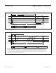
If the read time slots are 0 and 1, they are followed by a write-zero time slot.
If the read time slots are 1 and 0, they are followed by a write-one time slot.
If the read time slots are both 1 (error case), the subsequent write time slot is a write-one.
Typical Use
To perform a 1-Wire Search ROM sequence; a full sequence requires this command to be
executed 64 times to identify and address one device.
Restriction 1-Wire activity must have ended before the DS2482-100 can process this command.
Error Response
Command code and direction byte is not acknowledged if 1WB = 1 at the time the command
code is received and the command is ignored.
Command Duration
3 x t
SLOT
+ maximum 262.5ns, counted from the falling SCL edge of the first bit (MSB) of the
direction byte.
1-Wire Activity Begins maximum 262.5ns after the falling SCL edge of the MSB of the direction byte.
Read Pointer Position Status Register (for busy polling).
Status Bits Affected
1WB (set to 1 for 3 x t
SLOT
), SBR is updated at the first t
MSR
, TSB and DIR are updated at the
second t
MSR
(i.e., at t
SLOT
+ t
MSR
).
Configuration Bits Affected 1WS, APU apply.
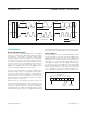
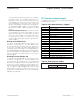
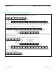
Table 3. Bit Allocation in the Direction Byte
BIT 7 BIT 6 BIT 5 BIT 4 BIT 3 BIT 2 BIT 1 BIT 0
V x x x x x x x
x = Don’t care.