
Datasheet


Maxim Integrated | 13www.maximintegrated.com
DS2482-100
Single-Channel 1-Wire Master
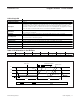
1-Wire Write Byte
Command Code A5h
Command Parameter Data Byte
Description Writes a single data byte to the 1-Wire line.
Typical Use
To write commands or data to the 1-Wire line. Equivalent to executing eight 1-Wire Single Bit
commands, but faster due to less I
2
C traffic.
Restriction 1-Wire activity must have ended before the DS2482-100 can process this command.
Error Response
Command code and data byte are not acknowledged if 1WB = 1 at the time the command code is
received and the command is ignored.
Command Duration 8 x t
SLOT
+ maximum 262.5ns, counted from falling edge of the last bit (LSB) of the data byte.
1-Wire Activity
Begins maximum 262.5ns after falling SCL edge of the LSB of the data byte (i.e., before the data
byte acknowledge). Note: The bit order on the I
2
C bus and the 1-Wire line is different (1-Wire: LSB
first; I
2
C: MSB first). Therefore, 1-Wire activity cannot begin before the DS2482-100 has received
the full data byte.
Read Pointer Position Status Register (for busy polling).
Status Bits Affected 1WB (set to 1 for 8 x t
SLOT
).
Configuration Bits Affected 1WS, SPU, APU apply.
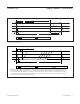
1-Wire Read Byte
Command Code 96h
Command Parameter None
Description
Generates eight read-data time slots on the 1-Wire line and stores result in the Read Data
Register.
Typical Use
To read data from the 1-Wire line. Equivalent to executing eight 1-Wire Single Bit commands with
V = 1 (write-one time slot), but faster due to less I
2
C traffic.
Restriction 1-Wire activity must have ended before the DS2482-100 can process this command.
Error Response
Command code is not acknowledged if 1WB = 1 at the time the command code is received and
the command is ignored.
Command Duration
8 x t
SLOT
+ maximum 262.5ns, counted from the falling SCL edge of the command code
acknowledge bit.
1-Wire Activity Begins maximum 262.5ns after the falling SCL edge of the command code acknowledge bit.
Read Pointer Position
Status Register (for busy polling). Note: To read the data byte received from the 1-Wire line, issue
the Set Read Pointer command and select the Read Data Register. Then access the DS2482-100
in read mode.
Status Bits Affected 1WB (set to 1 for 8 x t
SLOT
).
Configuration Bits Affected 1WS, APU apply.