
Datasheet


IO Voltage Range to GND........................................-0.5V to +6V
IO Sink Current....................................................................20mA
Operating Temperature Range.............................-40°C to +85°C
Junction Temperature
........................................................
+150°C
Storage Temperature Range..............................-55°C to +125°C
Lead Temperature (excluding UCSP, soldering, 10s).......+300°C
Soldering Temperature (reflow)
TO-92............................................................................+250°C
AIl other packages, excluding SFN
...............................
+260°C
(T
A
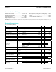
= -40°C to +85°C.) (Note 1)
PARAMETER SYMBOL CONDITIONS MIN TYP MAX UNITS
IO PIN: GENERAL DATA
1-Wire Pullup Voltage V
PUP
(Note 2) 2.8 5.25 V
1-Wire Pullup Resistance R
PUP
(Notes 2, 3) 0.3 2.2 kΩ
Input Capacitance C
IO
(Notes 4, 5) 1000 pF
Input Load Current I
L
IO pin at V
PUP
0.05 6.7 µA
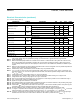
High-to-Low Switching Threshold V
TL
(Notes 5, 6, 7) 0.5
V
PUP
-
1.8
V
Input Low Voltage V
IL
(Notes 2, 8) 0.5 V
Low-to-High Switching Threshold V
TH
(Notes 5, 6, 9) 1.0
V
PUP
-
1.0
V
Switching Hysteresis V
HY
(Notes 5, 6, 10) 0.21 1.70 V
Output Low Voltage V
OL
At 4mA (Note 11) 0.4 V
Recovery Time
(Notes 2,12)
t
REC
Standard speed, R
PUP
= 2.2kΩ 5
µs
Overdrive speed, R
PUP
= 2.2kΩ 2
Overdrive speed, directly prior to reset
pulse; R
PUP
= 2.2kΩ
5
Rising-Edge Hold-Off Time (Notes
5, 13)
t
REH
Standard speed 0.5 5.0
µs
Overdrive speed Not applicable (0)
Time Slot Duration
(Notes 2, 14)
t
SLOT
Standard speed 65
µs
Overdrive speed 8
IO PIN: 1-Wire RESET, PRESENCE-DETECT CYCLE
Reset Low Time (Note 2) t
RSTL
Standard speed 480 640
µs
Overdrive speed 48 80
Presence-Detect High Time t
PDH
Standard speed 15 60
µs
Overdrive speed 2 6
Presence-Detect Low Time t
PDL
Standard speed 60 240
µs
Overdrive speed 8 24
Presence-Detect Sample Time
(Notes 2, 15)
t
MSP
Standard speed 60 75
µs
Overdrive speed 6 10
DS2431 1024-Bit, 1-Wire EEPROM
www.maximintegrated.com
Maxim Integrated
│
2
Absolute Maximum Ratings
Stresses beyond those listed under “Absolute Maximum Ratings” may cause permanent damage to the device. These are stress ratings only, and functional operation of the device at these
or any other conditions beyond those indicated in the operational sections of the specifications is not implied. Exposure to absolute maximum rating conditions for extended periods may affect
device reliability.
Electrical Characteristics