
Datasheet


DS2417
64-BIT LASERED ROM
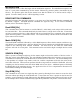
Each DS2417 contains a unique ROM code that is 64 bits long. The first eight bits are a 1-Wire family
code. The next 48 bits are a unique serial number. The last eight bits are a CRC of the first 56 bits. (See
Figure 3.) The 1-Wire CRC is generated using a polynomial generator consisting of a shift register and
XOR gates as shown in Figure 4. The polynomial is X
8
+ X
5
+ X
4
+ 1. Additional information about the
Dallas Semiconductor 1-Wire Cyclic Redundancy Check is available in Application Note 27. The shift
register bits are initialized to zero. Then starting with the least significant bit of the family code, one bit
at a time is shifted in. After the 8th bit of the family code has been entered, then the serial number is
entered. After the 48th bit of the serial number has been entered, the shift register contains the CRC
value. Shifting in the eight bits of CRC should return the shift register to all zeros. The 64-bit ROM and
ROM Function Control section allow the DS2417 to operate as a 1-Wire device and follow the 1-Wire
protocol detailed in the section "1-Wire Bus System".
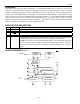
HIERARCHICAL STRUCTURE FOR 1-WIRE PROTOCOL Figure 2
3 of 15
DS2417
Command
Level
Available
Commands
Data Fields
Affected
1-Wire Bus
Bus
Other
Devices
Master
DS2417 specific
Function Commands
(see Figure 5)
Write Clock
Read Clock
RTC Counter, Device Control
RTC Counter, Device Control
Read ROM
Match ROM
Search ROM
Skip ROM
64-bit ROM
64-bit ROM
64-bit ROM
N/A
1-Wire ROM Function
Commands (see Figure 7)
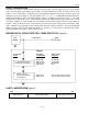
64-BIT LASERED ROM Figure 3
MSB LSB
8-Bit CRC Code 48-Bit Serial Number 8-Bit Family Code (27h)
MSB LSB MSB LSB MSB LSB