
Datasheet


DS2155
111 of 238
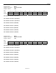
Register Name:
BOCC
Register Description:
BOC Control Register
Register Address:
37h
Bit # 7 6 5 4 3 2 1 0
Name — — — RBOCE RBR RBF1 RBF0 SBOC
Default 0 0 0 0 0 0 0 0
Bit 0/Send BOC (SBOC). Set = 1 to transmit the BOC code placed in bits 0 to 5 of the TFDL register.
Bits 1 and 2/Receive BOC Filter Bits (RBF0, RBF1). The BOC filter sets the number of consecutive patterns that
must be received without error prior to an indication of a valid message.
RBF1 RBF0
Consecutive BOC Codes for
Valid Sequence Identification
0 0 None
0 1 3
1 0 5
1 1 7
Bit 3/Receive BOC Reset (RBR). A 0-to-1 transition resets the BOC circuitry. Must be cleared and set again for a
subsequent reset.
Bit 4/Receive BOC Enable (RBOCE). Enables the receive BOC function. The RFDL register reports the received
BOC code and two information bits when this bit is set.
0 = receive BOC function disabled
1 = receive BOC function enabled; the RFDL register reports BOC messages and information
Bits 5 to 7/Unused, must be set to 0 for proper operation
Register Name:
RFDL
Register Description:
Receive FDL Register
Register Address:
C0h
Bit # 7 6 5 4 3 2 1 0
Name — — RBOC5 RBOC4 RBOC3 RBOC2 RBOC1 RBOC0
Default 0 0 0 0 0 0 0 0
RFDL register bit definitions when BOCC.4 = 1:
Bit 0/BOC Bit 0 (RBOC0)
Bit 1/BOC Bit 1 (RBOC1)
Bit 2/BOC Bit 2 (RBOC2)
Bit 3/BOC Bit 3 (RBOC3)
Bit 4/BOC Bit 4 (RBOC4)
Bit 5/BOC Bit 5 (RBOC5)
Bits 6, 7/This bit position is unused when BOCC.4 = 1.