
Datasheet


DS2155
50 of 238
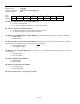
Register Name:
T1CCR1
Register Description:
T1 Common Control Register 1
Register Address:
07h
Bit # 7 6 5 4 3 2 1 0
Name — — — TRAI-CI TAIS-CI TFM PDE TLOOP
Default 0 0 0 0 0 0 0 0
Bit 0/Transmit Loop-Code Enable (TLOOP). See Section 25
for details.
0 = transmit data normally
1 = replace normal transmitted data with repeating code as defined in registers TCD1 and TCD2
Bit 1/Pulse Density Enforcer Enable (PDE). The framer always examines the transmit and receive data streams
for violations of these, which are required by ANSI T1.403: No more than 15 consecutive 0s and at least N 1s in
each and every time window of 8 x (N + 1) bits, where N = 1 through 23. Violations for the transmit and receive
data streams are reported in the INFO1.6 and INFO1.7 bits, respectively. When this bit is set to 1, the DS2155
forces the transmitted stream to meet this requirement no matter the content of the transmitted stream. When
running B8ZS, this bit should be set to 0 since B8ZS encoded data streams cannot violate the pulse density
requirements.
0 = disable transmit pulse density enforcer
1 = enable transmit pulse density enforcer
Bit 2/Transmit Frame Mode Select (TFM)
0 = D4 framing mode
1 = ESF framing mode
Bit 3/Transmit AIS-CI Enable (TAIS-CI). Setting this bit and the TBL bit (T1TCR1.1) causes the AIS-CI code
to be transmitted at TPOSO and TNEGO, as defined in ANSI T1.403.
0 = do not transmit the AIS-CI code
1 = transmit the AIS-CI code (T1TCR1.1 must also be set = 1)
Bit 4/Transmit RAI-CI Enable (TRAI-CI). Setting this bit causes the ESF RAI-CI code to be transmitted in the
FDL bit position.
0 = do not transmit the ESF RAI-CI code
1 = transmit the ESF RAI-CI code
Bits 5 to 7/Unused, must be set to 0 for proper operation