
Datasheet

DS21348/DS21Q348
53 of 76
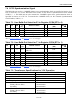
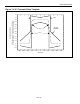
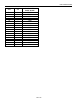
Figure 7-2. Protected Interface Using Internal Receive Termination
NOTES:
1. All resistor values are ±1%.
2. C1 = C2 = 0.1µF.
3. S is a 6V transient suppresser.
4. D1 to D8 are Schottky diodes.
5. The fuses are optional to prevent AC power line crosses from compromising the transformers.
6. Rp resistors exist to keep the Fuses from opening during a surge. If they are used, then the 60Ω
receive termination resistance must be adjusted to match the line impedance.
7. The Rt resistors are used to increase the transmitter return loss (Table 7-1
). No return loss is required
for T1 applications.
8. The transmit transformer turns ratio (N) would be 1:2 for 3.3V operation.
9. The 68µF is used to keep the local power plane potential within tolerance during a surge.
RTIP
RRING
TTIP
TRING
Receive
Line
N:1
(larger winding
toward the network)
DS21348
1.0µF
(non-
polarized)
VDD (21)
VSS (22)
0.1µF
VDD (36)
VSS (35)
0.1µF
+VDD
0.01µF
2.048MHz
(this clock can also
be 1.544MHz for T1
only applications)
MCLK
+VDD
S
C1
D1
D2
D3 D4
1:1
Rp
Fuse
Rp
Fuse
+VDD
C2
D5
D6
D7
D8
Rt
Rt
68µF
S
(optional)
Transmit
Line
Rp
Fuse
Rp
Fuse
(optional)
10µF
10µF
0.1µF
60 60