
Datasheet
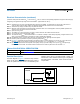

Hardware Conguration
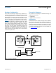
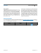
The 1-Wire bus has only a single line by definition; it is
important that each device on the bus be able to drive
it at the appropriate time. To facilitate this, each device
attached to the 1-Wire bus must have open-drain or three-
state outputs. The 1-Wire port of the DS1990A is open
drain with an internal circuit equivalent to that shown in
Figure 4. A multidrop bus consists of a 1-Wire bus with
multiple slaves attached. At standard speed, the 1-Wire
bus has a maximum data rate of 16.3kbps. The value
of the pullup resistor primarily depends on the network
size and load conditions. The idle state for the 1-Wire
bus is high. If for any reason a transaction needs to be
suspended, the bus must be left in the idle state if the
transaction is to resume. If this does not occur and the
busisleftlowformorethan120μs,oneormoredevices
on the bus may be reset.
Transaction Sequence
The protocol for accessing the DS1990A through the
1-Wire port is as follows:
● Initialization
● ROM Function Command
Initialization
All transactions on the 1-Wire bus begin with an initializa-
tion sequence. The initialization sequence consists of a
reset pulse transmitted by the bus master followed by
presence pulse(s) transmitted by the slave(s). The pres-
ence pulse lets the bus master know that the DS1990A is
on the bus and is ready to operate. For more details, see
the 1-Wire Signaling section.
Figure 4. Hardware Configuration
www.analog.com
Analog Devices
│
5
DS1990A Serial Number iButton
Rx
R
PUP
V
PUP
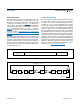
SIMPLE BUS MASTER
DS2480B BUS MASTER
OPEN-DRAIN
PORT PIN
100 MOSFET
Tx
Rx
Tx
DATA
DS1990A 1-Wire PORT
Rx = RECEIVE
Tx = TRANSMIT
V
DD
POL
RXD
SERIAL IN
SERIAL OUT
TXD
V
PP
GND
N.C.
1-W TO 1-Wire DATA
+5V
HOST CPU
SERIAL
PORT
DS2480B