
Datasheet
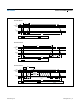

(Limits are 100% production tested at T
A
= +25°C and/or T
A
= +85°C. Limits over the operating temperature range and relevant supply
voltage range are guaranteed by design and characterization. Typical values at +25°C.)
Note 3: CapacitanceontheIOpincouldbe800pFwhenpowerisfirstapplied.Ifa5kΩresistorisusedtopulluptheIOlineto
V
PUP
5µs after power has been applied, the parasite capacitance will not affect normal communications.
Note 4: Guaranteed by design, simulation only. Not production tested.
Note 5: Maximum value represents the internal parasite capacitance when V
PUP
is first applied. Once the parasite capacitance is
charged, it does not affect normal communication.
Note 6: Input load is to ground.
Note 7: The voltage on IO must be less than or equal to V
ILMAX
whenever the master drives the line low.
Note 8: V
IH
is a function of the internal supply voltage.
Note 9: The reset low time (t
RSTL
) should be restricted to a maximum of 960µs to allow interrupt signaling. A longer duration could
mask or conceal interrupt pulses if this device is used in parallel with a DS1994.
Note 10: An additional reset or communication sequence cannot begin until the reset high time has expired.
Note 11: Presence pulse is guaranteed only after a preceding reset pulse (t
RSTL
).
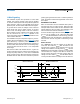
Note 12:εinFigure 7 represents the time required for the pullup circuitry to pull the voltage on IO up from V
IL
to V
IH
. The actual
maximum duration for the master to pull the line low is t
W1LMAX
+ t
F
-εandt
W0LMAX
+ t
F
-ε,respectively.
Note 13:δinFigure 7 represents the time required for the pullup circuitry to pull the voltage on IO up from V
IL
to the input-high
threshold of the bus master. The actual maximum duration for the master to pull the line low is t
RLMAX
+ t
F
.
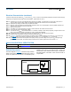
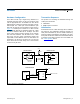
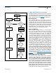
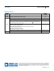
Detailed Description
The block diagram in Figure 1 shows the major function
blocks of the device. The DS1990A takes the energy it
needs to operate from the IO line, as indicated by the
parasite power block. The ROM function control unit
includes the 1-Wire interface and the logic to implement
the ROM function commands, which access 64 bits of
unique ROM.
Figure 1. Block Diagram
SIZE See the Package Information section.
WEIGHT (DS1990A) Ca. 2.5 grams
www.analog.com
Analog Devices
│
3
DS1990A Serial Number iButton
Electrical Characteristics (continued)
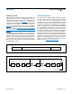
iButton CAN PHYSICAL SPECIFICATION
DS1990A
PARASITE POWER
ROM
FUNCTION CONTROL
IO
64-BIT
UNIQUE ROM