
Datasheet

IO Voltage Range to GND .................................... -0.5V to +6.0V
IO Sink Current DS1990A ..................................................20mA
IO Sink Current DS1990AA .............................................. ±10mA
Junction Temperature ...................................................... +125°C
Storage Temperature Range ............................ -55°C to +125°C
(Limits are 100% production tested at T
A
= +25°C and/or T
A
= +85°C. Limits over the operating temperature range and relevant supply
voltage range are guaranteed by design and characterization. Typical values at +25°C.)
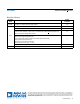
Electrical Characteristics
Note 1: System requirement.
Note 2: Full R
PUP
range is guaranteed by design and simulation and not production tested. Production testing performed at a fixed
R
PUP
value. Maximum allowable pullup resistance is a function of the number of 1-Wire devices in the system and 1-Wire
recovery times. The specified value here applies to systems with only one device and with the minimum 1-Wire recovery
times. For more heavily loaded systems, an active pullup such as that found in the DS2480B may be required.
PARAMETER SYMBOL CONDITIONS MIN TYP MAX UNITS
IO PIN: GENERAL DATA
1-Wire Pullup Voltage V
PUP
DS1990A (Note 1) 2.8 6.0 V
DS1990AA (Note 1) 3.0 5.25 V
1-Wire Pullup Resistance R
PUP
DS1990A (Notes 1 and 2) 0.6 5 kΩ
DS1990AA (Notes 1 and 2) 0.3 2.2 kΩ
Input Capacitance C
IO
DS1990A (Notes 3, 4, and 5) 100 800 pF
DS1990AA (Notes 4 and 5) 1000 pF
Input Load Current I
L
DS1990A (Note 6) 0.25 µA
DS1990AA IO pin at V
PUP
(Note 6) 0.05 1.75 6.7 µA
Input Low Voltage V
IL
(Notes 1 and 7) 0.3 V
Input High Voltage
V
IH
DS1990A (Notes 4 and 8) 2.2
V
DS1990AA (Notes 4 and 8)
0.75 x
V
PUP
Output Low Voltage V
OL
I
OL
= 4mA 0.4 V
Recovery Time t
REC
DS1990A (Note 1) 1 µs
DS1990AA (Note 1) 5 µs
Time Slot Duration t
SLOT
DS1990A (Note 1) 61 µs
DS1990AA (Note 1) 65 µs
IO PIN: 1-Wire RESET, PRESENCE-DETECT CYCLE
Reset Low Time t
RSTL
DS1990A (Notes 1 and 9) 480 µs
DS1990AA (Note 1) 480 640 µs
Reset High Time t
RSTH
(Notes 1 and 10) 480 µs
Presence-Detect High Time t
PDH
15 60 µs
Presence-Detect Low Time t
PDL
(Note 11) 60 240 µs
Presence-Detect Sample Time t
MSP
(Note 1) 60 75 µs
IO PIN: 1-Wire WRITE
Write-Zero Low Time t
W0L
(Notes 1 and 12) 60 120 µs
Write-One Low Time t
W1L
(Notes 1 and 12) 1 15 µs
IO PIN: 1-Wire READ
Read Low Time t
RL
(Notes 1 and 13) 1 15 - d µs
Read Sample Time t
MSR
(Notes 1 and 13) t
RL
+ d 15 µs
www.analog.com
Analog Devices
│
2
DS1990A Serial Number iButton
Absolute Maximum Ratings
Stresses beyond those listed under “Absolute Maximum Ratings” may cause permanent damage to the device. These are stress ratings only, and functional operation of the device at these
or any other conditions beyond those indicated in the operational sections of the specifications is not implied. Exposure to absolute maximum rating conditions for extended periods may affect
device reliability.