
Datasheet


DS1977
6 of 29
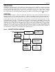
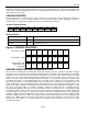
Figure 4. 1-WIRE CRC GENERATOR
X
0
X
1
X
2
X
3
X
4
X
5
X
6
X
7
X
8
POLYNOMIAL = X
8
+ X
5
+ X
4
+ 1
1
st
STAGE
2
nd
STAGE
3
rd
STAGE
4
th
STAGE
6
th
STAGE
5
th
STAGE
7
th
STAGE
8
th
STAGE
INPUT DATA
MEMORY
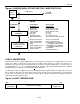
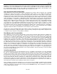
The memory map of the DS1977 is shown in Figure 5. The 32KB of general-purpose EEPROM are located in
pages 0 through 510. The passwords and the Password Control register take 17 bytes of page 511. The remaining
bytes of page 511 are not accessible to the user. The scratchpad is an additional page that acts as a buffer when
writing to the EEPROM memory or setting up a password, and when reading from the EEPROM.
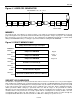
Figure 5. DS1977 MEMORY MAP
64-Byte Intermediate Storage Scratchpad
ADDRESS
0000h to
003Fh
64-Byte User EEPROM
Page 0
0040h to
7F7Fh
64-Byte User EEPROM
Pages 1
To 509
7F80h to
7FBFh
64-Byte User EEPROM
Page 510
7FC0h to
7FC7h
Read Access Password (A)
7FC8h to
7FCFh
Full Access Password (B)
7FD0h
Password Control Register
7FD1h to
7FFFh
(No Function; Will Read FFh, Cannot be Written)
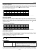
SECURITY BY PASSWORD
The DS1977 is designed to use two passwords that control read access and full access. No password applies
when reading from or writing to the scratchpad. Setting up a password or enabling/disabling the password checking
is done in the same way as writing data to a memory location, only the address is different. Since they are located
in the same memory page, both passwords can be redefined at the same time. Before changing passwords,
disable passwords. When setting up a password, make sure that all 8 bytes of the password are defined.
Otherwise the new password may be unknown. Always verify the scratchpad before issuing the copy scratchpad
command. After a new password is successfully copied from the scratchpad to its memory location, erase the
scratchpad by filling it with new data. Otherwise a copy of the password will remain accessible through the
scratchpad until the DS1977 is disconnected from the 1-Wire line or undergoes a power-on reset.