
Datasheet


DS1972
1024-Bit EEPROM i
Button
6 _______________________________________________________________________________________
1ST
STAGE
2ND
STAGE
3RD
STAGE
4TH
STAGE
7TH
STAGE
8TH
STAGE
6TH
STAGE
5TH
STAGE
X
0
X
1
X
2
X
3
X
4
POLYNOMIAL = X
8
+ X
5
+ X
4
+ 1
INPUT DATA
X
5
X
6
X
7
X
8
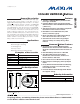
Figure 4. 1-Wire CRC Generator
commands is described in Figure 9. After a ROM
function command is successfully executed, the
memory functions become accessible and the master
can provide any one of the four memory function
commands. The protocol for these memory function
commands is described in Figure 7. All data is read
and written least significant bit first.
64-Bit Lasered ROM
Each DS1972 contains a unique ROM code that is 64
bits long. The first 8 bits are a 1-Wire family code. The
next 48 bits are a unique serial number. The last 8 bits
are a cyclic redundancy check (CRC) of the first 56 bits.
See Figure 3 for details. The 1-Wire CRC is generated
using a polynomial generator consisting of a shift regis-
ter and XOR gates as shown in Figure 4. The polynomial
is X
8
+ X
5
+ X
4
+ 1. Additional information about the
1-Wire CRC is available in Application Note 27:
Understanding and Using Cyclic Redundancy Checks
with Maxim i
Button Products
.
The shift register bits are initialized to 0. Then, starting
with the least significant bit of the family code, one bit
at a time is shifted in. After the 8th bit of the family code
has been entered, the serial number is entered. After
the last bit of the serial number has been entered, the
shift register contains the CRC value. Shifting in the 8
bits of the CRC returns the shift register to all 0s.
MSB
8-BIT
CRC CODE
48-BIT SERIAL NUMBER
MSB MSBLSB
LSB
LSB
8-BIT FAMILY CODE
(2Dh)
MSBLSB
Figure 3. 64-Bit Lasered ROM