
Datasheet


DS1921H/Z
6 of 45
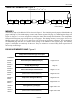
DS1921H/Z REGISTER PAGE MAP Figure 6
ADDR
b7
b6
b5
b4
b3
b2
b1
b0
Function
Access*
0200h
0
10 Seconds
Single Seconds
0201h
0
10 Minutes
Single Minutes
Real-
0202h
0
12/24
20h.
AM/PM
10h.
Single Hours
Time
Clock
R/W; R/W**
0203h
0
0
0
0
0
Day of Week
Registers
0204h
0
0
10 Date
Single Date
0205h
CENT
0
0
10m.
Single Months
0206h
10 Years
Single Years
0207h
MS
10 Seconds Alarm
Single Seconds Alarm
Real-
0208h
MM
10 Minutes Alarm
Single Minutes Alarm
Time
0209h MH 12/24
10ha.
A/P
10h.
alm.
Single Hours Alarm
Clock
Alarm
R/W; R/W**
020Ah
MD
0
0
0
0
Day of Week Alarm
Registers
020Bh
Temperature Low Alarm Threshold
Temp.
R/W; R/W**
020Ch
Temperature High Alarm Threshold
Alarms
020Dh
Number of Minutes Between Temperature Conversions
Sample
Rate
R/W; R**
020Eh
EOSC
EMCLR
0
EM
RO
TLS
THS
TAS
Control
R/W; R/W**
020Fh
(no function, reads 00h)
(N/A)
R; R**
0210h
(no function, reads 00h)
(N/A)
R; R**
0211h
Temperature Read Out (Forced Conversion)
Temp.
R; R**
0212h
Low Byte
Start
R/W; R/W**
0213h
High Byte
Delay
0214h
TCB
MEMCLR
MIP
SIP
0
TLF
THF
TAF
Status
R/W; R/W
0215h
Minutes
0216h
Hours
Mission
0217h
Date
Time
R; R
0218h
Month
Stamp
0219h
Year
021Ah
Low Byte
Mission
021Bh
Center Byte
Samples
R; R
021Ch
High Byte
Counter
021Dh
Low Byte
Device
021Eh
Center Byte
Samples
R; R
021Fh
High Byte
Counter
*The first entry in column ACCESS is valid between missions. The second entry shows the applicable
access mode while a mission is in progress.
**While a mission is in progress, these addresses can be read. The first attempt to write to these registers
(even read-only ones), however, will end the mission and overwrite selected writeable registers.
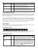
TIMEKEEPING
The RTC/alarm and calendar information is accessed by reading/writing the appropriate bytes in the
register page, address 200h to 206h. Note that some bits are set to 0. These bits will always read 0
regardless of how they are written. The contents of the time, calendar, and alarm registers are in the
Binary-Coded Decimal (BCD) format.