
Datasheet


DS1921H/Z
41 of 45
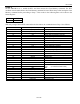
PARAMETER
SYMBOL
CONDITIONS
MIN
TYP
MAX
UNITS
NOTES
Presence Detect High
t
PDH
Standard Speed
15
60
µs
15
Time
Overdrive Speed
1.1
6
Presence Detect Low
t
PDL
Standard Speed
60
270
µs
15
Time
Overdrive Speed
7.5
24
Presence Detect
t
MSP
Standard Speed
60
75
µs
1, 16
Sample Time
Overdrive Speed
6
8.6
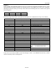
IO pin, 1-Wire Write
Write-0 Low Time
t
W0L
Standard Speed
60
120
µs
1, 11, 15
Overdrive Speed
6
15
Write-1 Low Time
t
W1L
Standard Speed
5
15
µs
1, 11
Overdrive Speed
1
2
IO pin, 1-Wire Read
Read Low Time
t
RL
Standard Speed
5
15 - δ
µs
1, 12
Overdrive Speed
1
2 - δ
Read Sample Time
t
MSR
Standard Speed
t
RL
+ δ
15
µs
1, 12
Overdrive Speed
t
RL
+ δ
2
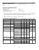
Real-Time Clock
Frequency Deviation
∆
F
-5°C to +46°C
-48
+46
PPM
Temperature Converter
Tempcore Operating
T
TC
DS1921H
15
46
°C
Range
DS1921Z
-5
+26
Conversion Time
t
CONV
75
360
ms
Thermal Response
Time Constant
τ
RESP
130
s
13
Conversion Error
∆ϑ
-1
+1
°C
17, 18
Number of
Conversions
N
CONV
(see lifetime graphs) — 14, 16
NOTES
1)
System Requirement.
2)
Maximum allowable pull-up resistance is a function of the number of 1-Wire devices in the
system and 1-Wire recovery times. The specified value here applies to systems with only one
device and with the minimum 1-Wire recovery times. For more heavily loaded systems, an active
pull-up such as that found in the DS2480B may be required.
3)
Capacitance on IO could be 800pF when power is first applied. If a 2.2kΩ resistor is used to pull
up the data line, 2.5µs after V
PUP
has been applied the parasite capacitor will not affect normal
communication.
4)
Input load is to ground.
5)
All voltages are referenced to ground.
6)
V
TL
and V
TH
are functions of the internal supply voltage, which is a function of V
PUP
and the
1-Wire recovery times. The V
TH
and V
TL
maximum specifications are valid at V
PUP
= 5.25V. In
any case, V
TL
< V
TH
< V
PUP
.
7)
Voltage below which, during a falling edge on IO, a logic 0 is detected.
8)
The voltage on IO needs to be less or equal to V
ILMAX
whenever the master drives the line low.
9)
Voltage above which, during a rising edge on IO, a logic 1 is detected.
10)
The I-V characteristic is linear for voltages less than 1V.