
Datasheet


DS1921H/Z
37 of 45
STEP 2
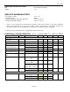
Set the EMCLR bit to 1, enable the RTC and then execute the Clear Memory command. The RTC
oscillator must be stable before the Clear Memory command is issued. Wait 500 µs after issuing the Clear
Memory command before proceeding to Step 3. This results in the following data to be written to the
Status Register:
Address:
20Eh
Data:
40h
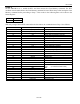
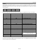
With only a single DS1921H/Z connected to the bus master, the communication of step 2 is as follows:
MASTER MODE
DATA (LSB FIRST)
COMMENTS
TX
(Reset)
Reset pulse (480μs to 960µs)
RX
(Presence)
Presence pulse
TX
CCh
Issue Skip ROM command
TX
0Fh
Issue Write Scratchpad command
TX
0Eh
TA1, beginning offset = 0Eh
TX
02h
TA2, address = 020Eh
TX
40h
Write status byte to scratchpad
TX
(Reset)
Reset pulse
RX
(Presence)
Presence pulse
TX
CCh
Issue Skip ROM command
TX
AAh
Issue Read Scratchpad command
RX
0Eh
Read TA1, beginning offset = 0Eh
RX
02h
Read TA2, address = 020Eh
RX
0Eh
Read E/S, ending offset = 0Eh, flags = 0h
RX
40h
Read scratchpad data and verify
TX
(Reset)
Reset pulse
RX
(Presence)
Presence pulse
TX
CCh
Issue Skip ROM command
TX
55h
Issue Copy Scratchpad command
TX
0Eh
TA1
TA2 (AUTHORIZATION CODE)
E/S
TX
02h
TX
0Eh
TX
(Reset)
Reset pulse
RX
(Presence)
Presence pulse
TX
CCh
Issue Skip ROM command
TX
3Ch
Issue Clear Memory command
TX
(Reset)
Reset pulse
RX
(Presence)
Presence pulse