
Datasheet


DS1921H/Z
7 of 45
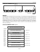
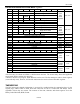
RTC and RTC Alarm Register Bitmap
ADDR
b7
b6
b5
b4
b3
b2
b1
b0
0200h
0
10 Seconds
Single Seconds
0201h
0
10 Minutes
Single Minutes
0202h
0
12/24
20h.
AM/PM
10h.
Single Hours
0203h
0
0
0
0
0
Day of Week
0204h
0
0
10 Date
Single Date
0205h
CENT
0
0
10m.
Single Months
0206h
10 Years
Single Years
0207h
MS
10 Seconds Alarm
Single Seconds Alarm
0208h
MM
10 Minutes Alarm
Single Minutes Alarm
0209h MH 12/24
10ha.
A/P
10h.
alm.
Single Hours Alarm
020Ah
MD
0
0
0
0
Day of Week Alarm
RTC/Calendar
The RTC of the DS1921H/Z can run in either 12-hour or 24-hour mode. Bit 6 of the Hours Register
(address 202h) is defined as the 12- or 24-hour mode select bit. When high, the 12-hour mode is selected.
In the 12-hour mode, bit 5 is the AM/PM bit with logic 1 being PM. In the 24-hour mode, bit 5 is the 20-
hour bit (20 to 23 hours).
To distinguish between the days of the week the DS1921H/Z includes a counter with a range from 1 to 7.
The assignment of counter value to the day of week is arbitrary. Typically, the number 1 is assigned to a
Sunday (U.S. standard) or to a Monday (European standard).
The calendar logic is designed to automatically compensate for leap years. For every year value that is
either 00 or a multiple of 4 the device will add a 29
th
of February. This will work correctly up to (but not
including) the year 2100.
The DS1921H/Z is Y2K-compliant. Bit 7 (CENT) of the Months Register at address 205h serves as a
century flag. When the Year Register rolls over from 99 to 00 the century flag will toggle. It is
recommended to write the century bit to a 1 when setting the RTC to a time/date between the years 2000
and 2099.
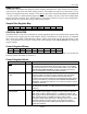
RTC Alarms
The DS1921H/Z also contains a RTC alarm function. The alarm registers are located in registers 207h to
20Ah. The most significant bit of each of the alarm registers is a mask bit. When all of the mask bits are
logic 0, an alarm will occur once per week when the values stored in timekeeping registers 200h to 203h
match the values stored in the time of day alarm registers. Any alarm will set the Timer Alarm Flag
(TAF) in the device's Status Register (address 214h). The bus master may set the Search Conditions in the
Control Register (address 20Eh) to identify devices with timer alarms by means of the Conditional Search
function (see ROM Function Commands).