
Datasheet


DS1921H/Z
5 of 45
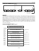
1-Wire CRC GENERATOR Figure 4
X
0
X
1
X
2
X
3
X
4
X
5
X
6
X
7
X
8
Polynomial =
X
8
+ X
5
+ X
4
+ 1
1
st
STAGE
2
nd
STAGE
3
rd
STAGE
4
th
STAGE
6
th
STAGE
5
th
STAGE
7
th
STAGE
8
th
STAGE
INPUT DATA
MEMORY
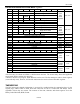
The memory map of the DS1921H/Z is shown in Figure 5. The 4096-bit general-purpose SRAM make up
pages 0 through 15. The timekeeping, control, and counter registers fill page 16, called Register Page (see
Figure 6). Pages 17 to 19 are assigned to storing the alarm time stamps and durations. The temperature
histogram bins begin at page 64 and use up to four pages. The datalog memory covers pages 128 to 191.
Memory pages 20 to 63, 68 to 127, and 192 to 255 are reserved for future extensions. The scratchpad is
an additional page that acts as a buffer when writing to the SRAM or the register page. The memory
pages 17 and higher are read-only for the user. They are written to or erased solely under supervision of
the on-chip control logic.
DS1921H/Z MEMORY MAP Figure 5
32-Byte Intermediate Storage Scratchpad
ADDRESS
0000h to
01FFh
General-Purpose SRAM (16 Pages)
Pages 0 to 15
0200h to
021Fh
32-Byte Register Page
Page 16
0220h to
027Fh
Alarm Time Stamps and Durations
Pages 17 to 19
0280h to
07FFh
(Reserved for Future Extensions) Pages 20 to 63
0800h to
087Fh
Temperature Histogram Memory
Pages 64 to 67
0880h to
0FFFh
(Reserved for Future Extensions) Pages 68 to 127
1000h to
17FFh
Datalog Memory (64 Pages)
Pages 128 to 191
1800h to
1FFFh
(Reserved for Future Extensions) Pages 192 to 255