
Datasheet


DS1921H/Z
42 of 45
11)
ε in Figure 15 represents the time required for the pull-up circuitry to pull the voltage on IO up
from V
IL
to V
TH
. The actual maximum duration for the master to pull the line low is t
W1LMAX
+ t
F
-
ε and t
W0LMAX
+ t
F
- ε, respectively.
12)
δ in Figure 15 represents the time required for the pull-up circuitry to pull the voltage on IO up
from V
IL
to the input high threshold of the bus master. The actual maximum duration for the
master to pull the line low is t
RLMAX
+ t
F
.
13)
This number was derived from a test conducted by Cemagref in Antony, France, in July of 2000.
http://www.cemagref.fr/English/index.htm Test Report No. E42
14)
The number of temperature conversions (= Samples) possible with the built-in energy source
depends on the operating and storage temperature of the device. When not in use for a mission,
the RTC oscillator should be turned off and device should be stored at a temperature not
exceeding +25°C. Under this condition the shelf life time is 10 years minimum.
15)
Highlighted numbers are not in compliance with the published iButton device standards. See
comparison table below.
16)
These values are derived from simulation across process, voltage, and temperature and are not
production tested.
17)
Total accuracy is ∆ϑ plus 1/16°C quantization due to the 1/8°C digital resolution of the device.
18)
WARNING: Maxim data logger products are 100% tested and calibrated at time of manufacture
to ensure that they meet all data sheet parameters, including temperature accuracy. As with any
sensor-based product, user shall be responsible for occasionally rechecking the temperature
accuracy of the product to ensure it is still operating properly. Furthermore, as with all products of
this type, when deployed in the field and subjected to handling, harsh environments, or other
hazards/use conditions, there may be some extremely small but non-zero logger failure rate. In
applications where the failure of any logger is a concern, user shall assure that redundant (or other
primary) methods of testing and determining the handling methods, quality, and fitness of the
articles and products are implemented to further mitigate any risk.
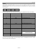
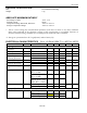
Standard Values
DS1921H/Z Values
Parameter
Standard Speed
Overdrive Speed
Standard Speed
Overdrive Speed
Name
min
max
min
max
min
max
min
max
t
SLOT
(incl. t
REC
)
61µs
(undef.)
7µs
(undef.)
65µs
1)
(undef.)
8µs
1)
(undef.)
t
RSTL
480µs
(undef.)
48µs
80µs
540µs
640µs
48µs
80µs
t
PDH
15µs
60µs
2µs
6µs
15µs
60µs
1.1µs
6µs
t
PDL
60µs
240µs
8µs
24µs
60µs
270µs
7.5µs
24µs
t
W0L
60µs
120µs
6µs
16µs
60µs
120µs
6µs
15µs
1) Intentional change, longer recovery time between time slots.