
Datasheet


DS1921H/Z
39 of 45
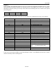
STEP 4
In this example, the temperature alarms are set to 0°C for the low temperature threshold and 10°C for the
high temperature threshold, assuming it is a DS1921Z device. The sample rate is once every 10 minutes,
allowing the mission to last up to 14 days. This results in the following data to be written to the special
function registers:
Address:
20Bh
20Ch
20Dh
Data:
2Ch
7Ch
0Ah
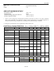
With only a single DS1921H/Z connected to the bus master, the communication of step 4 is as follows:
MASTER MODE
DATA (LSB FIRST)
COMMENTS
TX
(Reset)
Reset pulse (480μs to 960µs)
RX
(Presence)
Presence pulse
TX
CCh
Issue Skip ROM command
TX
0Fh
Issue Write Scratchpad command
TX
0Bh
TA1, beginning offset = 0Bh
TX
02h
TA2, address = 020Bh
TX
<3 data bytes>
Write 3 bytes of data to scratchpad
TX
(Reset)
Reset pulse
RX
(Presence)
Presence pulse
TX
CCh
Issue Skip ROM command
TX
AAh
Issue Read Scratchpad command
RX
0Bh
Read TA1, beginning offset = 0Bh
RX
02h
Read TA2, address = 020Bh
RX
0Dh
Read E/S, ending offset = 0Dh, flags = 0h
RX
<3 data bytes>
Read scratchpad data and verify
TX
(Reset)
Reset pulse
RX
(Presence)
Presence pulse
TX
CCh
Issue Skip ROM command
TX
55h
Issue Copy Scratchpad command
TX
0Bh
TA1
TA2 (AUTHORIZATION CODE)
E/S
TX
02h
TX
0Dh
TX
(Reset)
Reset pulse
RX
(Presence)
Presence pulse
If step 4 was successful, the MIP bit in the Status Register will be 1, the MEMCLR bit will be 0, and the
mission start delay will be counting down.