
Datasheet


DS1921H/Z
31 of 45
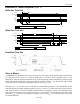
READ/WRITE TIMING DIAGRAM Figure 15
Write-One Time Slot
RESISTOR MASTER
V
PUP
V
IHMASTER
V
TH
V
TL
V
ILMAX
0V
t
F
t
SLOT
t
W1L
ε
Write-Zero Time Slot
RESISTOR MASTER
t
REC
V
PUP
V
IHMASTER
V
TH
V
TL
V
ILMAX
0V
t
F
t
SLOT
t
W0L
ε
Read-Data Time Slot
Slave to Master
A read-data time slot begins like a write-one time slot. The voltage on the data line must remain below
V
TL
until the read low time t
RL
is expired. During the t
RL
window, when responding with a 0, the
DS1921H/Z will start pulling the data line low; its internal timing generator determines when this pull-
down ends and the voltage starts rising again. When responding with a 1, the DS1921H/Z will not hold
the data line low at all, and the voltage starts rising as soon as t
RL
is over.
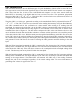
The sum of t
RL
+ δ (rise time) on one side and the internal timing generator of the DS1921H/Z on the
other side define the master sampling window (t
MSRMIN
to t
MSRMAX
) in which the master must perform a
read from the data line. For most reliable communication, t
RL
should be as short as permissible and the
master should read close to but no later than t
MSRMAX
. After reading from the data line, the master must
wait until t
SLOT
is expired. This guarantees sufficient recovery time t
REC
for the DS1921H/Z to get ready
for the next time slot.