
Datasheet


DS1920
8 of 22
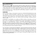
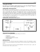
1-Wire CRC CODE Figure 6
MEMORY
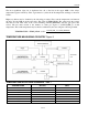
The DS1920’s memory is organized as shown in Figure 7. The memory consists of a scratchpad and 2
bytes of EEPROM that store the high and low temperature triggers TH and TL. The scratchpad helps
insure data integrity when communicating over the 1-Wire bus. Data is first written to the scratchpad
where it can be read back. After the data has been verified, a copy scratchpad command will transfer the
data to the EEPROM. This process ensures data integrity when modifying the memory.
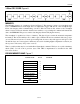
The scratchpad is organized as 8 bytes of memory. The first 2 bytes contain the measured temperature
information. The 3rd and 4th bytes are volatile copies of TH and TL and are refreshed with every power-
on reset. The next 2 bytes are not used; upon reading back, however, they will appear as all logic 1s. The
7th and 8th bytes are count registers, which may be used in obtaining higher temperature resolution (see
the Operation—Measuring Temperature section).
There is a 9th byte that may be read with a Read Scratchpad command. This byte is a cyclic redundancy
check (CRC) over all of the 8 previous bytes. This CRC is implemented as described in the CRC
Generation section.
DS1920 MEMORY MAP Figure 7
SCRATCHPAD
BYTE
EEPROM
TEMPERATURE LSB
0
TEMPERATURE MSB
1
TH/USER BYTE 1
2
TH/USER BYTE 1
TL/USER BYTE 2
3
TL/USER BYTE 2
RESERVED
4
RESERVED
5
COUNT REMAIN
6
COUNT PER °C
7
CRC
8