
Datasheet


DS1920
6 of 22
OPERATION—ALARM SIGNALING
After the DS1920 has performed a temperature conversion, the temperature value is compared to the
trigger values stored in TH and TL. Since these registers are 8 bits only, the 0.5°C bit is ignored for
comparison. The most significant bit of TH or TL directly corresponds to the sign bit of the 16-bit
temperature register. If the result of a temperature measurement is higher than TH or lower than TL, an
alarm flag inside the device is set. This flag is updated with every temperature measurement. As long as
the alarm flag is set, the DS1920 will respond to the alarm search command. This allows many DS1920s
to be connected in parallel doing simultaneous temperature measurements. If somewhere the temperature
exceeds the limits, the alarming device(s) can be identified and read immediately without having to read
nonalarming devices.
64-BIT LASERED ROM
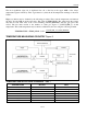
Each DS1920 contains a unique ROM code that is 64 bits long. The first 8 bits are a 1-Wire family code
(DS1920 code is 10h). The next 48 bits are a unique serial number. The last 8 bits are a CRC of the first
56 bits. (See Figure 4.) The 64-bit ROM and ROM Function Control section allow the DS1920 to operate
as a 1-Wire device and follow the 1-Wire protocol detailed in the 1-Wire Bus System section. The
memory and control functions of the DS1920 are not accessible until the ROM function protocol has been
satisfied. This protocol is described in the ROM function protocol flowchart (Figure 5). The 1-Wire bus
master must first provide one of five ROM function commands: 1) Read ROM, 2) Match ROM, 3) Search
ROM, 4) Skip ROM, or 5) Alarm Search. After a ROM function sequence has been successfully
executed, the functions specific to the DS1920 are accessible and the bus master may then provide any
one of the five memory and control function commands.
CRC GENERATION
The DS1920 has an 8-bit CRC stored in the most significant byte of the 64-bit ROM. The bus master can
compute a CRC value from the first 56 bits of the 64-bit ROM and compare it to the value stored within
the DS1920 to determine if the ROM data has been received error-free by the bus master. The equivalent
polynomial function of this CRC is:
CRC = X
8
+ X
5
+ X
4
+ 1
The DS1920 also generates an 8-bit CRC value using the same polynomial function shown above and
provides this value to the bus master to validate the transfer of data bytes. In each case where a CRC is
used for data transfer validation, the bus master must calculate a CRC value using the polynomial
function given above and compare the calculated value to either the 8-bit CRC value stored in the 64-bit
ROM portion of the DS1920 (for ROM reads) or the 8-bit CRC value computed within the DS1920
(which is read as a 9th byte when the scratchpad is read). The comparison of CRC values and decision to
continue with an operation are determined entirely by the bus master. There is no circuitry inside the
DS1920 that prevents a command sequence from proceeding if the CRC stored in or calculated by the
DS1920 does not match the value generated by the bus master.
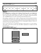
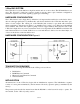
The 1-Wire CRC can be generated using a polynomial generator consisting of a shift register and XOR
gates as shown in Figure 6. Additional information about the Maxim 1-Wire Cyclic Redundancy Check is
available in the Book of iButton Standards.
The shift register bits are first initialized to 0. For the ROM section, starting with the least significant bit
of the family code, 1 bit at a time is shifted in. After the 8th bit of the family code has been entered, then
the serial number is entered. After the 48th bit of the serial number has been entered, the shift register
contains the CRC value. Shifting in the 8 bits of CRC should return the shift register to all 0s.