
Datasheet


DS1920
20 of 22
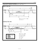
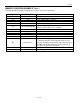
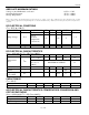
AC ELECTRICAL CHARACTERISTICS: 1-Wire INTERFACE
(V
PUP
= 2.8V to 6.0V, T
A
= -55°C to +100°C.)
PARAMETER
SYMBOL
MIN
TYP
MAX
UNITS
NOTES
Time Slot
t
SLOT
60
120
µs
Write 1 Low Time
t
LOW1
1
15
µs
Write 0 Low Time
t
LOW0
60
120
µ
s
Read Data Valid
t
RDV
exactly 15
µ
s
Release Time
t
RELEASE
0
15
45
µ
s
Read Data Setup
t
SU
1
µs
8
Recovery Time
t
REC
1
µ
s
Reset Time High
t
RSTH
480
µs
Reset Time Low
t
RSTL
480
4800
µ
s
6, 7
Presence Detect High
t
PDHIGH
15
60
µ
s
Presence Detect Low
t
PDLOW
60
240
µs
NOTES:
1. Temperature conversion will work with ±2°C accuracy down to V
PUP
= 3.4V.
2. All voltages are referenced to ground.
3. I
DD
specified with low-impedance pullup to 5.0V.
4. Active current refers to temperature conversion.
5. Writing to EEPROM consumes approximately 200µA.
6. t
RSTL
may be up to 4800µs. With longer times, the result of temperature conversion may get lost.
7. The reset low time should be restricted to a maximum of 960µs, to allow interrupt signaling,
otherwise it could mask or conceal interrupt pulses.
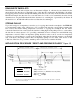
8. Read data setup time refers to the time the host must pull the 1-Wire bus low to read a bit. Data is
guaranteed to be valid within 1µs of this falling edge and will remain valid for 14µs minimum (15µs
total from falling edge on 1-Wire bus).
9. Capacitance on the data contact could be 800pF when power is first applied. If a 5kΩ resistor is used
to pull up the data line to V
CC
, 5µs after power has been applied, the parasite capacitance will not
affect normal communications.
10. Under certain low-voltage conditions, V
ILMAX
may have to be reduced to as much as 0.5V to always
guarantee a presence pulse.
11. See the Typical Performance Curve for specification limits outside the 0°C to +70°C range.
Thermometer error reflects sensor accuracy as tested during calibration.