
Datasheet


DS1920
2 of 22
iButton DESCRIPTION
The DS1920 Temperature iButton provides 9-bit temperature readings, which indicate the temperature of
the device. Information is sent to/from the DS1920 over a 1-Wire interface. Power for reading, writing,
and performing temperature conversions is derived from the data line itself. Because each DS1920
contains a unique silicon serial number, multiple DS1920s can exist on the same 1-Wire bus. This allows
for placing temperature sensors in many different places. Applications where this feature is useful include
HVAC environmental controls, sensing temperatures inside buildings, equipment or machinery, and in
process monitoring and control.
OVERVIEW
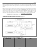
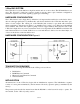
The block diagram of Figure 1 shows the major components of the DS1920. The DS1920 has three main
data components: 1) 64-bit lasered ROM, 2) temperature sensor, and 3) nonvolatile temperature alarm
triggers TH and TL. The device derives its power from the 1-Wire communication line by storing energy
on an internal capacitor during periods of time when the signal line is high and continues to operate off
this power source during the low times of the 1-Wire line until it returns high to replenish the parasite
(capacitor) supply.
Communication to the DS1920 is via a 1-Wire port. With the 1-Wire port, the memory and control
functions will not be available before the ROM function protocol has been established. The master must
first provide one of five ROM function commands: 1) Read ROM, 2) Match ROM, 3) Search ROM, 4)
Skip ROM, or 5) Alarm Search. These commands operate on the 64-bit lasered ROM portion of each
device and can single out a specific device if many are present on the 1-Wire line as well as indicate to
the bus master how many and what types of devices are present. After a ROM function sequence has been
successfully executed, the memory and control functions are accessible and the master may then provide
any one of the five memory and control function commands.
One control function command instructs the DS1920 to perform a temperature measurement. The result
of this measurement will be placed in the DS1920’s scratchpad memory, and may be read by issuing a
memory function command, which reads the contents of the scratchpad memory. The temperature alarm
triggers TH and TL consist of 1 byte of EEPROM each. If the alarm search command is not applied to the
DS1920, these registers may be used as general-purpose user memory. Writing TH and TL is done using
a memory function command. Read access to these registers is through the scratchpad. All data is read
and written least significant bit first.