
Datasheet


DS1920
15 of 22
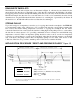
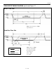
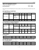
READ/WRITE TIME SLOTS
The definitions of write and read time slots are illustrated in Figure 11. All time slots are initiated by the
master driving the data line low. The falling edge of the data line synchronizes the DS1920 to the master
by triggering a delay circuit in the DS1920. During write time slots, the delay circuit determines when the
DS1920 will sample the data line. For a read data time slot, if a 0 is to be transmitted, the delay circuit
determines how long the DS1920 will hold the data line low overriding the 1 generated by the master. If
the data bit is a 1, the DS1920 will leave the read data time slot unchanged.
STRONG PULLUP
To provide energy for a temperature conversion or for copying data from the scratchpad to the EEPROM,
a low-impedance pullup of the 1-Wire bus to 5V is required just after the corresponding command has
been sent by the master. During temperature conversion or copying the scratchpad, the bus master
controls the transition from a state where the data line is idling high via the pullup resistor to a state where
the data line is actively driven to 5V, providing a minimum of 1mA of current for each DS1920 doing
temperature conversion. This low impedance pullup should be active for 0.75 seconds for temperature
conversion or at least 10ms for copying to the scratchpad. After that, the data line returns to an idle high
state controlled by the pullup resistor. The low-impedance pullup does not affect other devices on the
1-Wire bus. Therefore, it is possible to multidrop other 1-Wire devices with the DS1920.
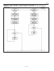
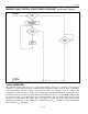
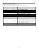
INITIALIZATION PROCEDURE “RESET AND PRESENCE PULSES” Figure 10
480µs ≤ t
RSTL
< ∞ ∗
480µs ≤ t
RSTH
< ∞ (includes recovery time)
15µs ≤ t
PDH
< 60µs
60µs ≤ t
PDL
< 240µs
RESISTOR
MASTER
DS1920
*
In order not to mask interrupt signaling by other devices on the 1-Wire bus, t
RSTL
+ t
R
should
always be less than 960
µ
s.