
Datasheet


DS1920
14 of 22
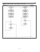
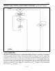
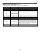
MEMORY AND CONTROL FUNCTIONS FLOWCHART (continued) Figure 9
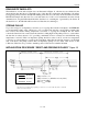
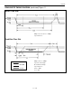
1-Wire SIGNALING
The DS1920 requires strict protocols to ensure data integrity. The protocol consists of five types of
signaling on one line: Reset Sequence with Reset Pulse and Presence Pulse, Write 0, Write 1, Read Data
and Strong Pullup. All these signals except Presence Pulse are initiated by the bus master. The
initialization sequence required to begin any communication with the DS1920 is shown in Figure 10. A
Reset Pulse followed by a Presence Pulse indicates the DS1920 is ready to accept a ROM command. The
bus master transmits (Tx) a Reset Pulse (t
RSTL
, minimum 480µs). The bus master then releases the line
and goes into receive mode (Rx). The 1-Wire bus is pulled to a high state via the pullup resistor. After
detecting the rising edge on the 1-Wire line, the DS1920 waits (t
PDH
, 15–60µs) and then transmits the
Presence Pulse (t
PDL
, 60–240µs).