
Datasheet


DS1881
Dual NV Audio Taper Digital Potentiometer
____________________________________________________________________ 11
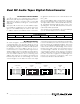
Configuration Register
If 10 is entered as the value of the two MSBs of the
Command Byte, then the Configuration Register is to
be modified. The three LSBs of the Configuration
Register control the NV/volatile wiper setting, the zero-
crossing detection feature, and the potentiometer atten-
uation configuration.
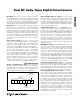
CONFIGURATION REGISTER
Factory Default: 87h
Memory Type: NV (EEPROM)
1 0 X X X
V/NV
CONTROL
ZERO-
CROSSING
POT
CONFIG
b7 b6 b5 b4 b3 b2 b1 b0
bits 7, 6
Configuration Selection: When bit 7 is set to a 1 and bit 6 is set to a 0, the following configuration bits can be set
and stored in EEPROM.
bits 5, 4, 3 These bits have no function.
bit 2
Volatile/Nonvolatile Potentiometer Register Control Bit: A control bit that sets the potentiometer registers to be
either volatile or nonvolatile memory.
0 = Potentiometer registers are set to nonvolatile memory storage.
1 = Potentiometer registers are set to volatile memory storage. On power-up, the potentiometer wipers are in the
mute position (default).
bit 1
Zero-Crossing Detection Enable Bit: A bit used to enable and disable the zero-crossing functionality.
0 = Zero-crossing detection is disabled.
1 = Zero-crossing detection is enabled (default).
bit 0
Potentiometer Position Configuration: A control bit used to select the number of positions both potentiometers
have.
0 = Potentiometers have 63 positions and mute.
1 = Potentiometers have 33 positions and mute (default).