
Datasheet


1 of 18 042902
FEATURES
§ Three linear taper potentiometers
- Two 10kW, 100-position
- One 100kW, 256-position
§ 248 bytes of user EEPROM memory
§ Monitors microprocessor power supply,
voltage sense, and external override
§ Access to data and potentiometer control
through a 2-wire interface
§ External write-protect (WP) pin to protect
data and potentiometer settings
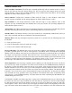
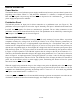
PIN CONFIGURATION
§ Operates from a 5V supply
§ Nonvolatile (NV) wiper storage
§ Packaging: 20-pin TSSOP
§ Programming temperature: 0ºC to +70ºC
§ Industrial operating temperature:
-40ºC to +85ºC
ORDERING INFORMATION
DS1846E-010
DS1846E-010/T&R (Tape-and-Reel Version)
PIN DESCRIPTION
V
CC
– Power-Supply Input
GND – Ground
SDA – 2-Wire Serial Data
Input/Output
SCL – 2-Wire Serial Clock Input
WP – Write-Protect Input
A0 – Address Input
H0, H1, H2 – High End of Potentiometer
L0, L1, L2 – Low End of Potentiometer
W0, W1, W2 – Wiper Terminal of
Potentiometer
PBRST – Pushbutton Reset Input
NMI – Nonmaskable Interrupt
Output
IN – NMI Voltage Input
RST – Active-Low Reset Output
RST – Active-High Reset Output
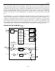
OVERVIEW
The DS1846 NV tri-potentiometer, memory, and MicroMonitor™ consists of two 10kW, 100-position
linear taper potentiometers, one 100kW, 256-position linear taper potentiometer; 256 bytes of EEPROM
memory; and a MicroMonitor. The device provides an ideal method for setting bias voltages and currents
in control applications using a minimum of circuitry.
DS1846
NV Tri-Potentiometer,
Memory, and MicroMonito
r
www.maxim-ic.com
SDA
SCL
A0
WP
NMI
L0
W1
L1
L2
GND
V
CC
IN
PBRST
RST
RST
H0
W0
H1
W2
H2
20-Pin TSSOP
20
19
18
17
16
15
14
13
12
11
MicroMonitor is a trademark of Dallas Semiconductor.
1
2
3
4
5
6
7
8
9
10