
Datasheet


DS1685/DS1687 3V/5V Real-Time Clocks
16 of 34
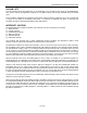
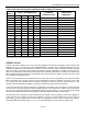
Table 3. Periodic Interrupt Rate and Square-Wave Output Frequency
EXT.
REG B
SELECT BITS REGISTER A
t
PI
PERIODIC
INTERRUPT RATE
SQW OUTPUT
FREQUENCY
E32K RS3 RS2 RS1 RS0
0 0 0 0 0 None None
0 0 0 0 1 3.90625ms 256Hz
0 0 0 1 0 7.8125ms 128Hz
0 0 0 1 1
122.070µs
8.192kHz
0 0 1 0 0
244.141µs
4.096kHz
0 0 1 0 1
488.281µs
2.048kHz
0 0 1 1 0
976.5625µs
1.024kHz
0 0 1 1 1 1.953125ms 512Hz
0 1 0 0 0 3.90625ms 256Hz
0 1 0 0 1 7.8125ms 128Hz
0 1 0 1 0 15.625ms 64Hz
0 1 0 1 1 31.25ms 32Hz
0 1 1 0 0 62.5ms 16Hz
0 1 1 0 1 125ms 8Hz
0 1 1 1 0 250ms 4Hz
0 1 1 1 1 500ms 2Hz
1 X X X X * 32.768kHz
*RS3–RS0 determine periodic interrupt rates as listed for E32K = 0.
UPDATE CYCLE
The RTC executes an update cycle once per second regardless of the SET bit in Register B. When the SET bit in
Register B is set to 1, the user copy of the double-buffered time, calendar, alarm, and elapsed time byte is frozen
and does not update as the time increments. However, the time countdown chain continues to update the internal
copy of the buffer. This feature allows the time to maintain accuracy independent of reading or writing the time,
calendar, and alarm buffers and also guarantees that time and calendar information is consistent. The update cycle
also compares each alarm byte with the corresponding time byte and issues an alarm if a match or if a “don’t care”
code is present in all alarm locations.
There are three methods that can handle access of the RTC that avoid any possibility of accessing inconsistent
time and calendar data. The first method uses the update-ended interrupt. If enabled, an interrupt occurs after
every update cycle that indicates that over 999ms is available to read valid time and date information. If this
interrupt is used, the IRQF bit in Register C should be cleared before leaving the interrupt routine.
A second method uses the UIP bit in Register A to determine if the update cycle is in progress. The UIP bit pulses
once per second. After the UIP bit goes high, the update transfer occurs 244µs later. If a low is read on the UIP bit,
the user has at least 244µs before the time/calendar data is changed. Therefore, the user should avoid interrupt
service routines that would cause the time needed to read valid time/calendar data to exceed 244µs.
The third method uses a periodic interrupt to determine if an update cycle is in progress. The UIP bit in Register A
is set high between the setting of the PF bit in Register C (Figure 4). Periodic interrupts that occur at a rate of
greater than t
BUC
allow valid time and date information to be reached at each occurrence of the periodic interrupt.
The reads should be complete within (t
PI
/ 2 + t
BUC
) to ensure that data is not read during the update cycle.