
Datasheet

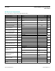


PIN NAME FUNCTION
1 EVENT
Event Input. The EVENT pin is the input the DS1682 monitors to determine when an event occurs. When
the pin is pulled high, the contents of the EEPROM are transferred to the ETC and the oscillator starts.
The ETC begins to count in quarter-second increments. When the EVENT pin falls to logic 0, the event
counter increments, and the event counter, ETC, and user-memory data are stored in the EEPROM array.
When the EVENT pin changes states, the 2-wire bus is unavailable for communications for t
EW
(falling)
and t
ER
(rising). The EVENT input is also deglitched (t
G
) to prevent short noise spikes from triggering an
event.
2, 7 N.C. No Connection. These pins are not connected internally.
3 ALARM
Active-Low Alarm Output. The DS1682 monitors the values in the ETC for the programmed value in
the alarm register. When the ETC matches the alarm value, the alarm ag (AF) is set. Once set, the
alarm ag cannot be reset. See the operating descriptions for the AOS and AP
bits for details about the
operation of the ALARM pin.
4 GND Ground
5 SCL
2-Wire Serial-Clock Input. The SCL pin is the serial-clock input for the 2-wire synchronous
communications channel. The SCL pin is an input that requires an external pullup resistor.
6 SDA
2-Wire Input/Output. The SDA pin is the data input/output signal for the 2-wire synchronous
communications channel. The SDA pin is an open-drain I/O, which requires an external pullup resistor.
8 V
CC
+2.5V to +5.5V Input Supply
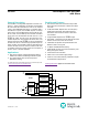
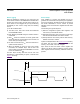
EVENT
+
N.C.
ALARM
1
2
3
4
8
7
6
5GND
V
CC
N.C.
SDA
SCL
SO
(150 mils)
TOP VIEW
DS1682
DS1682 Total-Elapsed-Time Recorder
with Alarm
www.maximintegrated.com
Maxim Integrated
│
5
Pin Description
Pin Conguration