
Datasheet

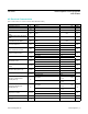


PARAMETER SYMBOL CONDITIONS MIN TYP MAX UNITS
EEPROM Endurance E
E
(Note 2) 50k writes
EEPROM Write Time t
EW
(Notes 1, 3, 4) 150 300 ms
EEPROM Transfer to RAM t
ER
(Notes 1, 5) 1 ms
ALARM Output Active-Low Pulse
Width
t
SL
(Note 1) 62.5 ms
ALARM Output Active-High Pulse
Width
t
SH
(Note 1) 437.5 ms
ALARM Input Pulled Low
and Released Pulse Width
t
SPL
(Note 1) 500 ms
SCL Clock Frequency f
SCL
Fast mode 400
kHz
Standard mode 100
Bus Free Time Between a
STOP and START Condition
t
BUF
Fast mode 1.3
µs
Standard mode 4.7
Hold Time (Repeated)
START Condition (Note 6)
t
HD:STA
Fast mode 0.6
µs
Standard mode 4.0
Low Period of SCL t
LOW
Fast mode 1.3
µs
Standard mode 4.7
High Period of SCL t
HIGH
Fast mode 0.6
µs
Standard mode 4.0
Setup Time for a Repeated
START
t
SU:STA
Fast mode 0.6
µs
Standard mode 4.0
Data Hold Time (Notes 7, 8) t
HD:DAT
Fast mode 0
µs
Standard mode 0
Data Setup Time (Note 9) t
SU:DAT
Fast mode 100
ns
Standard mode 250
Rise Time of SDA and SCL
Signals (Note 10)
t
R
Fast mode
20 +
0.1C
B
300
ns
Standard mode
20 +
0.1C
B
1000
Fall Time of SDA and SCL
Signals (Note 10)
t
F
Fast mode
20 +
0.1C
B
300
ns
Standard mode
20 +
0.1C
B
300
Setup Time for STOP t
SU:STO
Fast mode 0.6
µs
Standard mode 4.0
Input Capacitance C
I/O
(Note 1) 10 pF
Capacitive Load for Each
Bus Line
C
B
(Note 10) 400 pF
DS1682 Total-Elapsed-Time Recorder
with Alarm
www.maximintegrated.com
Maxim Integrated
│
3
AC Electrical Characteristics
(V
CC
= 2.5V to 5.5V, T
A
= -40°C to +85°C, unless otherwise noted.)