
Datasheet


DS1672
6 of 15
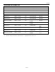
POWER-UP/POWER-DOWN CHARACTERISTICS
(T
A
= -40°C to +85°C)
PARAMETER SYMBOL MIN TYP MAX UNITS
V
CC
Detect to RST (V
CC
Falling) t
RPD
10 µs
V
CC
Detect to RST (V
CC
Rising)
(Note 11)
t
RPU
250 ms
V
CC
Fall Time; V
PF(MAX)
to V
PF(MIN)
t
F
300
µs
V
CC
Rise Time; V
PF(MIN)
to V
PF(MAX)
t
R
0
µs
Note 11: If the EOSC bit in the control register is set to logic 1, t
RPU
is equal to 250ms plus the startup time of the crystal oscillator.
Warning: Negative undershoots below –0.3V while the part is in battery-backed mode can cause
loss of data.
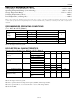
Figure 1. Timing Diagram
SCL
START
SDA
STOP
t
BUF
REPEATED
START
t
HD:STA
t
LOW
t
HD:STA
t
HD:DAT
t
SU:DAT
t
HIGH
t
SU:STA
t
F
t
SU:STO
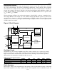
Figure 2. Power-Up/Power-Down Timing
OUTPUTS
V
CC
V
PF(max)
INPUTS
HIGH IMPEDANCE
RST
DON'T CARE
VALID
RECOGNIZED
RECOGNIZED
VALID
t
RPD
V
PF(min)
t
F
t
PD
t
R
t
RPU