
Datasheet


DS1670
7 of 16
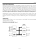
The DS1670 nonvolatilizes the external SRAM(s) by write protecting the SRAM(s) and by providing a
back-up power supply in the absence of V
CC
. When V
CC
falls below 2.88V (typical), access to the
external SRAM(s) are prohibited by forcing CEOL and CEOH high regardless of the level of CEI , BLE ,
and
BHE . Also at this point, the SRAM power supply (V
CCO
) is switched from V
CC
to V
BAT
. Upon power-
up, access is prohibited until the end of t
RPU
.
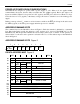
EXTERNAL SRAM CHIP ENABLE Table 3
CEI
BHE
BLE
CEOL CEOH
FUNCTION
0 0 0 0 0 Word Transfer
0 0 1 1 0 Byte Transfer in upper half of data bus (D15-D8)
0 1 0 0 1 Byte Transfer in lower half of data bus (D7-D0)
0 1 1 1 1 External SRAMs disabled
1 X X 1 1 External SRAMs disabled
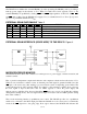
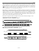
EXTERNAL SRAM INTERFACE (WORD-WIDE) TO THE DS1670 Figure 4
MICROPROCESSOR MONITOR
The DS1670 monitors three vital conditions for a microprocessor: power supply, software execution, and
external override.
First, a precision temperature-compensated reference and comparator circuit monitors the status of V
CC
.
When an out-of-tolerance condition occurs, an internal power-fail signal is generated which forces the
RST
pin to the active state, thus warning a processor-based system of impending power failure. The
power-fail trip point is 2.88V (typical). When V
CC
returns to an in-tolerance condition upon power-up,
the reset signal is kept in the active state for 250ms (typical) to allow the power supply and
microprocessor to stabilize. Note, however, that if the
EOSC bit is set to a logic 1 (to disable the oscillator
during battery-backup mode), the reset signal will be kept in an active state for 250ms plus the startup
time of the oscillator.
The second monitoring function is pushbutton reset control. The DS1670 provides for a pushbutton
switch to be connected to the RST output pin. When the DS1670 is not in a reset cycle, it continuously
monitors the
RST signal for a low-going edge. If an edge is detected, the DS1670 will debounce the