
Datasheet


DS1554 256k, Nonvolatile, Y2K-Compliant Timekeeping RAM
9 of 18
Table 3. Alarm Mask Bits
AM4 AM3 AM2 AM1 ALARM RATE
1 1 1 1 Once per second
1 1 1 0 When seconds match
1 1 0 0 When minutes and seconds match
1 0 0 0 When hours, minutes, and seconds match
0 0 0 0 When date, hours, minutes, and seconds match
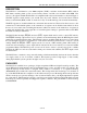
When the RTC Register values match Alarm Register settings, the Alarm Flag bit (AF) is set to a 1. If
Alarm Flag Enable (AE) is also set to a 1, the alarm condition activates the IRQ/FT pin. The IRQ/FT
signal is cleared by a read or write to the Flags Register (Address 7FF0h) as shown in Figure 2 and 3.
When CE is active, the IRQ/FT signal may be cleared by having the address stable for as short as 15 ns
and either OE or WE active, but is not guaranteed to be cleared unless t
RC
is fulfilled. The alarm flag is
also cleared by a read or write to the Flags Register but the flag will not change states until the end of the
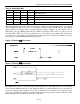
read/write cycle and the IRQ/FT signal has been cleared.
Figure 2. Clearing IRQ Waveforms
Figure 3. Clearing IRQ Waveforms
The IRQ/FT pin can also be activated in the battery-backed mode. The IRQ/FT will go low if an alarm
occurs and both ABE and AE are set. The ABE and AE bits are cleared during the power-up transition,
however an alarm generated during power-up will set AF. Therefore, the AF bit can be read after system
power-up to determine if an alarm was generated during the power-up sequence. Figure 4 illustrates alarm
timing during the battery-backup mode and power-up states.
0V
CE,
CE=0