
Datasheet


DS1553 64kB, Nonvolatile, Year-2000-Compliant Timekeeping RAM
8 of 20
USING THE CLOCK ALARM
The alarm settings and control for the DS1553 reside within registers 1FF2h–1FF5h. Register 1FF6h
contains two alarm-enable bits: Alarm Enable (AE) and Alarm in Backup Enable (ABE). The AE and
ABE bits must be set as described below for the IRQ /FT output to be activated for a matched alarm
condition.
The alarm can be programmed to activate on a specific day of the month or repeat every day, hour,
minute, or second. It can also be programmed to go off while the DS1553 is in the battery-backed state of
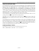
operation to serve as a system wakeup. Alarm mask bits AM1–AM4 control the alarm mode. Table 3
shows the possible settings. Configurations not listed in the table default to the once-per-second mode to
notify the user of an incorrect alarm setting.
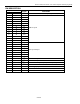
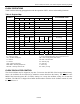
Table 3. Alarm Mask Bits
AM4 AM3 AM2 AM1 ALARM RATE
1 1 1 1 Once per second
1 1 1 0 When seconds match
1 1 0 0 When minutes and seconds match
1 0 0 0 When hours, minutes, and seconds match
0 0 0 0 When date, hours, minutes, and seconds match
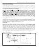
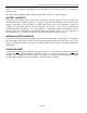
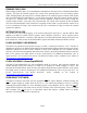
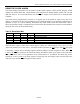
When the RTC register values match Alarm register settings, the Alarm Flag bit (AF) is set to 1. If the
Alarm Flag Enable (AE) is also set to 1, the alarm condition activates the IRQ /FT pin. The IRQ /FT signal
is cleared by a read or write to the Flags register (Address 1FF0h) as shown in Figures 2 and 3. When CE
is active, the
IRQ
/FT signal may be cleared by having the address stable for as short as 15ns and either
OE or WE active, but it is not guaranteed to be cleared unless t
RC
is fulfilled. The alarm flag is also
cleared by a read or write to the Flags register, but the flag does not change states until the end of the
read/write cycle and the IRQ /FT signal has been cleared.