
Datasheet


DS1553 64kB, Nonvolatile, Year-2000-Compliant Timekeeping RAM
6 of 20
CLOCK OPERATIONS
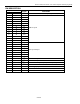
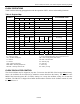
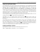
Table 2 and the following paragraphs describe the operation of RTC, alarm, and watchdog functions.
Table 2. Register Map
DATA
ADDRESS
B
7
B
6
B
5
B
4
B
3
B
2
B
1
B
0
FUNCTION/RANGE
1FFFh 10 Year Year Year 00-99
1FFEh X X X 10 M Month Month 01-12
1FFDh X X 10 Date Date Date 01-31
1FFCh X FT X X X Day Day 01-07
1FFBh X X 10 Hour Hour Hour 00-23
1FFAh X 10 Minutes Minutes Minutes 00-59
1FF9h OSC 10 Seconds Seconds Seconds 00-59
1FF8h W R 10 Century Century Control 00-39
1FF7h WDS
BMB
4
BMB3 BMB2
BMB
1
BMB
0
RB
1
RB0 Watchdog
1FF6h AE Y ABE Y Y Y Y Y Interrupts
1FF5h AM4 Y 10 Date Date Alarm Date 01-31
1FF4h AM3 Y 10 Hours Hours Alarm Hours 00-23
1FF3h AM2 10 Minutes Minutes Alarm Minutes 00-59
1FF2h AM1 10 Seconds Seconds Alarm Seconds 00-59
1FF1h Y Y Y Y Y Y Y Y Unused —
1FF0h WF AF 0 BLF 0 0 0 0 Flags —
X = Unused, Read/Writable Under Write and Read Bit Control AE = Alarm Flag Enable
FT = Frequency Test Bit Y = Unused, Read/Writable Without Write and Read Bit Control
OSC = Oscillator Start/Stop Bit
ABE = Alarm in Battery-Backup Mode Enable
W = Write Bit AM1–AM4 = Alarm Mask Bits
R = Read Bit WF = Watchdog Flag
WDS = Watchdog Steering Bit AF = Alarm Flag
BMB0–BMB4 = Watchdog Multiplier Bits 0 = 0 Read Only
RB0–RB1 = Watchdog Resolution Bits BLF = Battery Low Flag
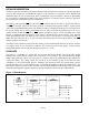
CLOCK OSCILLATOR CONTROL
The clock oscillator may be stopped at any time. To increase the shelf life of the backup lithium battery
source, the oscillator can be turned off to minimize current drain from the battery. The
OSC bit is the
MSB of the Seconds register (B7 of 1FF9h). Setting it to 1 stops the oscillator; setting it to 0 starts the
oscillator. The DS1553 is shipped from Dallas Semiconductor with the clock oscillator turned off, with
the
OSC bit set to 1.