
Datasheet
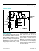
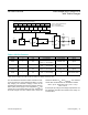

Hundredths-of-Seconds Generator
The hundredths-of-seconds generator circuit shown in
the functional diagram is a state machine that divides the
incoming frequency (4096Hz) by 41 for 24 cycles and
40 for one cycle. This produces a 100Hz output that is
slightly off during the short term, and is exactly correct
every 250ms. The divide ratio is given by:
Ratio = [41 x 24 + 40 x 1] / 25 = 40.96
Thus, the long-term average frequency output is exactly
the desired 100Hz.
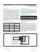
Clock and Calendar
The time and calendar information is obtained by reading
the appropriate register bytes. See Table 3 for the RTC
registers. The time and calendar are set or initialized by
writing the appropriate register bytes. The contents of the
time and calendar registers are in the binary-coded deci-
mal (BCD) format. The day-of-week register increments
at midnight. Values that correspond to the day-of-week
are user-defined but must be sequential (i.e., if 1 equals
Sunday, then 2 equals Monday, and so on). Illogical
time and date entries result in undefined operation. The
DS1390–DS1393 can run in either 12-hour or 24-hour
mode. Bit 6 of the hours register is defined as the 12- or
24-hour mode-select bit. When high, the 12-hour mode
is selected. In the 12-hour mode, bit 5 is the AM/PM bit
with logic high being PM. In the 24-hour mode, bit 5 is
the second 10-hour bit (20 to 23 hours). Changing the
12/24-hour mode-select bit requires that the hours data
be re-entered, including the alarm register (if used). The
century bit (bit 7 of the month register) is toggled when the
years register overflows from 99 to 00.
Note: Unless otherwise specified, the state of the registers is not defined when power (V
CC
and V
BACKUP
) is first applied.
X = General-purpose read/write bit.
0 = Always reads as zero.
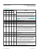
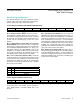
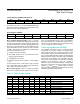
Table 3. Address Map (continued)
WRITE
ADDRESS
READ
ADDRESS
BIT 7 BIT 6 BIT 5 BIT 4 BIT 3 BIT 2 BIT 1 BIT 0 FUNCTION RANGE
8Bh 0Bh AM3 12/24
AM/PM
10
Hour
Hour Alarm Hours
1–12 + AM/
PM
00–23 BCD
10 Hour
8Ch 0Ch AM4 DY/DT 10 Date
Day Alarm Day 1–7 BCD
Date Alarm Date 01–31 BCD
8Dh 0Dh EOSC
0 BBSQI RS2 RS1 INTCN 0 AIE
Control
DS1390/93/94
0 X X X X 0 X DS1391
0 BBSQI RS2 RS1 ESQW 0 AIE DS1392
8Eh 0Eh OSF 0 0 0 0 0 0 AF Status —
8Fh 0Fh TCS3 TCS2 TCS1 TCS0 DS1 DS0 ROUT1 ROUT0
Trickle
Charger
—
www.maximintegrated.com
Maxim Integrated
│
16
DS1390–DS1394 Low-Voltage SPI/3-Wire RTCs
with Trickle Charger